TRANSMISSION
4.9L
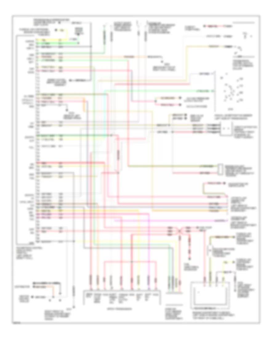
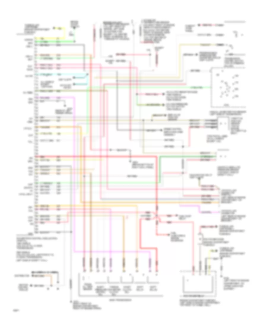
4.9L, Transmission Wiring Diagram for Ford Pickup F250 1994

List of elements for 4.9L, Transmission Wiring Diagram for Ford Pickup F250 1994:
- gnd
- (1993 models) a/c clutch diode (1994 models)
- (1994 models)
- (4.9l-right front of engine, near intake runner #1)
- (5.0l & 5.8l-top center front of engine, near intake runner #6)
- (7.5l-top center of engine, behind distributor)
- (behind bottom of right cowl panel)
- (engine compartment
- (except 7.5l-center front of engine, on thermostat housing)
- (left rear of engine compartment, on bracket)
- (left side of safety wall)
- (rear of left fender apron)
- (top of engine, on throttle body)
- (tps pigtail used on all models except 4.9l)
- 1993 m0dels (4.9l,5.0l,5.8l,5.8l lightning & 7.5l w/ e4od transmission)
- 1994 m0dels (4.9l,5.8l & 7.5l w/ e40d transmission)
- 4.9l
- 4x4 hi/low ind sw
- 4x4 ind
- A/c clutch resistor diode
- A/c high pressure cut out switch
- Accs
- All models except lightning
- Assembly
- Boo
- Brake on/off switch
- Ccs
- Ckp
- Coast clutch sol
- Column)
- Compartment, on
- Distributor
- Dlc
- E40d transmission
- Ect
- Egr valve position sensor
- Elect pressure control sol
- Engine compartment fuse box (left side of engine compartment, top front of wheel well)
- Engine coolant temperature sensor (7.5l-left front of engine, left side of distributor)
- Epc
- Except
- Except 4.9l
- Fuel injectors & engine solenoids
- Fuel pump relay
- Fuse #17 (fuse
- Fuse box)
- Fusible link cartridge i
- Fusible link cartridge i (engine compartment
- Fusible link cartridge u (engine compartment
- G101 (right front of engine compartment, front of fender apron)
- G104
- G108 (left front of engine
- G203
- Gnd
- Iat
- Ign
- Ign
- Ignition control module
- Inst clstr
- Intake air temperature sensor
- Kapwr
- Malfunction ind lp (inst clstr)
- Manifold absolute pressure sensor (top right side of safety wall)
- Manual lever position sensor (left side of transmission)
- Map
- Mil feed
- Mlp
- Nca
- Off
- Panel)
- Pcm power diode
- Pcm power relay
- Powertrain control module (pcm) (partial)
- Programmable speedometer/ odometer module (inst clstr)
- Red
- Servo/amplifier
- Shift sol #1
- Shift sol #2
- Sig rtn
- Speed control
- Ss1
- Ss2
- Support)
- Tcc
- Tcil
- Tcs
- Tft
- Throttle position sensor
- Torque converter clutch sol
- Trans oil temp sensor
- Transmission control switch (top of steering
- Upper radiator
- Vip data link connector
- Vip data link connector (partial)
- Vip dl input
- Vip dlc
- Vref
- Vss (+)
- Vss (-)
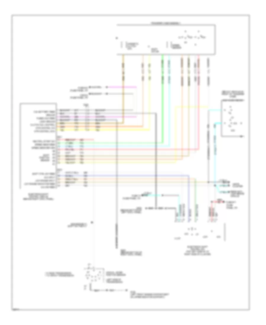
Transfer Case Wiring Diagram for Ford Pickup F250 1994
List of elements for Transfer Case Wiring Diagram for Ford Pickup F250 1994:
- (below vehicle on front of transfer case)
- (fuse
- (left side of transmission)
- * w/ e40d transmission ** w/ 4r70w transmission
- 4x2
- 4x4
- 4x4 hi/low ind sw
- 4x4 ind feed
- 4x4 input
- 5**
- 8**
- C.b. battery feed
- C/b #12 (fuse panel i/p)
- C221
- C222
- C223
- Clutch coil control
- Electronic shift control module (behind right cowl panel)
- Electronic shift control sw (top left side of i/p,
- Fuse #17
- Fuse #18 (fuse panel i/p)
- Fuse 10 (fuse panel i/p)
- Fused acc feed
- G108 (left front engine compartment on upper radiator support))
- G200 (behind bottom of left cowl panel)
- G203 (behind bottom of right cowl panel)
- Gas engine w/ shift on the fly
- Ground
- Illum
- Instr cluster
- Logic ground
- Low
- Low range indicator feed
- Low range input
- Magnetic clutch coil
- Manual lever position sensor
- Mtr control ccw
- Mtr control cw
- Neutral start sw
- Panel i/p)
- Rear anti- lock brake module
- Red/
- Right side of cluster)
- Sensor
- Shift ctrl sw feed
- Shift motor
- Shift position
- Speed sens feed
- Speed sens return
- Speed sensor
- Transfer case assembly
5.0L
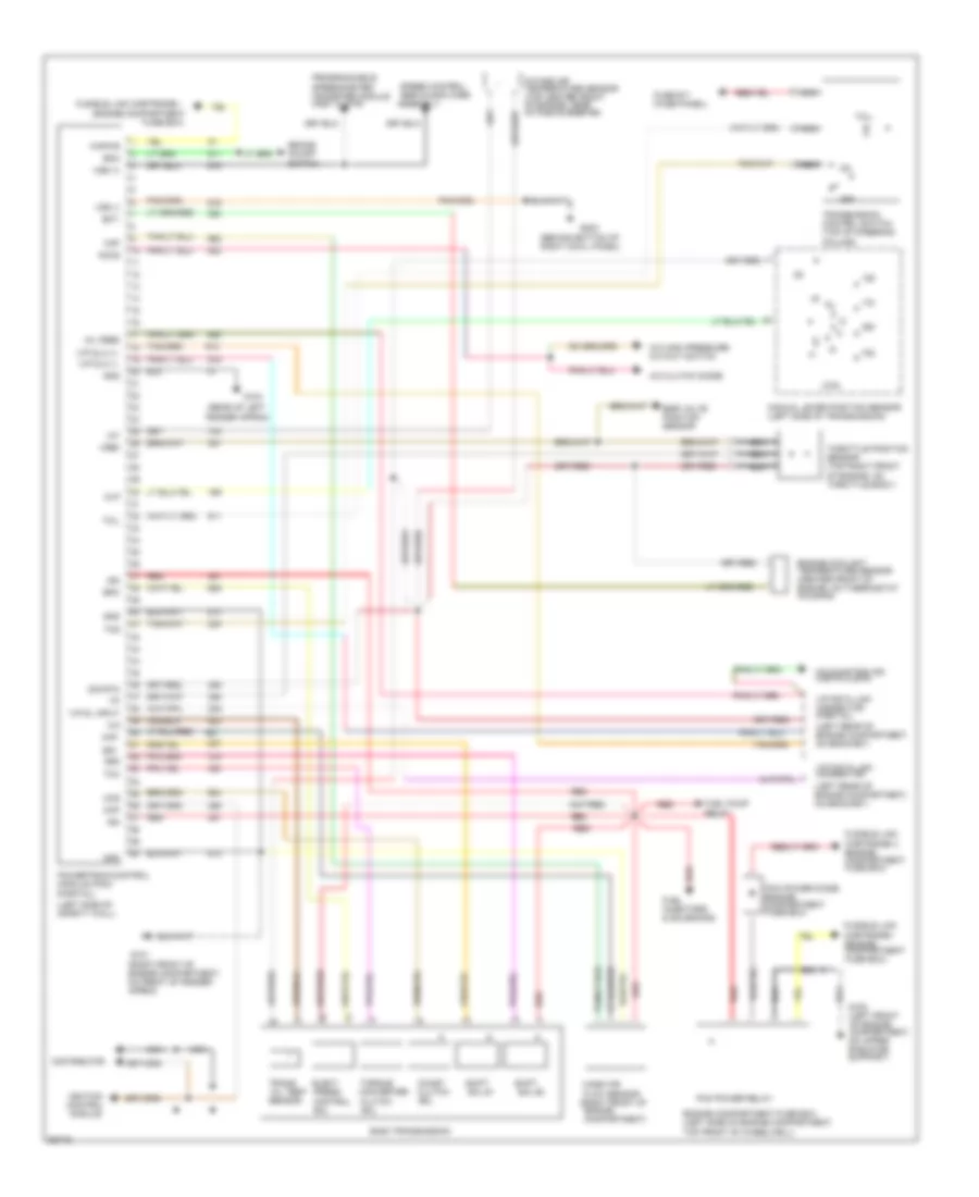
5.0L, 4R7OW Transmission Wiring Diagram for Ford Pickup F250 1994
List of elements for 5.0L, 4R7OW Transmission Wiring Diagram for Ford Pickup F250 1994:
- (behind bottom of right cowl panel)
- (engine compartment
- (left rear of engine compartment, on bracket)
- (left side of safety wall)
- (left side of transmission)
- (rear of left
- (right front of engine compartment, on front of fender apron)
- 4r70w transmission
- A/c clutch diode
- A/c high pressure
- Accs
- Boo
- Brake on/off switch
- Ckp
- Column)
- Conv clutch
- Cutout switch
- Distributor
- Ect
- Egr valve position sensor
- Elect
- Engine compartment fuse box (left side of engine compartment,
- Engine coolant temperature sensor (center front of engine, on thermostat housing)
- Epc
- Fender apron)
- Fuel injectors & solenoids
- Fuel pump relay
- Fuse #17 (fuse panel)
- Fuse box)
- Fusible link cartridge i (engine compartment fuse box)
- Fusible link cartridge u (engine compartment fuse box)
- Fusible link cartridge i
- G101
- G104
- G108 (left front of engine compartment, on upper radiator support)
- G203
- Gnd
- Iat
- Ign
- Ignition control module
- Intake air temperature sensor (top center front of engine, near intake runner #6)
- Kapwr
- Maf
- Mafs
- Malfunction ind (instr clstr)
- Manual lever position sensor
- Mass air flow sensor (right front of engine compartment)
- Mil feed
- Mlp
- Nca
- Of engine, on throttle body)
- Off
- Oss
- Output shaft speed sensor (left rear of transmission)
- Pcm power diode (engine compartment fuse box)
- Pcm power relay
- Powertrain control module (pcm) (partial)
- Press ctrl sol
- Programmable speedometer/ odometer module (inst clstr)
- Pwr
- Red
- Sens rtn
- Shift sol
- Sig rtn
- Sol
- Speed control servo/amplifier assembly
- Ss1
- Ss2
- Tcc
- Tcil
- Tcs
- Tft
- Throttle position sensor (top right front
- Top front of wheelwell)
- Torque
- Trans fluid temp sens
- Transmission control switch (top of steering
- Vip data link connector
- Vip data link connector (partial)
- Vip dl input
- Vip dlc (+)
- Vip dlc (-)
- Vref
- Vss (+)
- Vss (-)
5.0L, E4OD Transmission Wiring Diagram for Ford Pickup F250 1994
List of elements for 5.0L, E4OD Transmission Wiring Diagram for Ford Pickup F250 1994:
- (behind bottom of right cowl panel)
- (engine compartment
- (left rear of engine compartment, on bracket)
- (left side of safety wall)
- (partial)
- (rear of left
- A/c clutch diode
- A/c high pressure cutout switch
- Accs
- Assembly
- Boo
- Brake on/off switch
- Ccs
- Ckp
- Clutch
- Coast clutch
- Column)
- Control
- Converter
- Distributor
- E40d transmission
- Ect
- Egr valve position sensor
- Elect
- Engine compartment)
- Engine compartment fuse box (left side of engine compartment,
- Engine coolant temperature sensor (center front of engine, on thermostat housing)
- Epc
- Fender apron)
- Fuel injectors & solenoids
- Fuel pump relay
- Fuse #17 (fuse panel)
- Fuse box)
- Fusible link cartridge i (engine compartment fuse box)
- Fusible link cartridge u (engine compartment fuse box)
- Fusible link cartridge i
- G101 (right front of engine compartment, on front of fender apron)
- G104
- G108 (left front of engine compartment, on upper radiator support)
- G203
- Gnd
- Iat
- Ign
- Ignition control module
- Intake air temperature sensor (top center front of engine, near intake runner #6)
- Kapwr
- Maf
- Malfunction ind (instr clstr)
- Manual lever position sensor (left side of transmission)
- Mass air flow sensor (right front of
- Mil feed
- Mlp
- Nca
- Of engine, on throttle body)
- Off
- Oil temp sensor
- Pcm power diode (engine compartment fuse box)
- Pcm power relay
- Powertrain control module (pcm)
- Press
- Programmable speedometer/ odometer module (inst clstr)
- Red
- Servo/amplifier
- Shift
- Sig rtn
- Sol
- Sol #1
- Sol #2
- Speed control
- Ss1
- Ss2
- Tcc
- Tcil
- Tcs
- Tft
- Throttle position sensor (top right front
- Top front of wheelwell)
- Torque
- Trans
- Transmission control switch (top of steering
- Vip data link connector
- Vip data link connector (partial)
- Vip dl input
- Vip dlc (+)
- Vip dlc (-)
- Vref
- Vss (+)
- Vss (-)
Transfer Case Wiring Diagram for Ford Pickup F250 1994
List of elements for Transfer Case Wiring Diagram for Ford Pickup F250 1994:
- (below vehicle on front of transfer case)
- (fuse
- (left side of transmission)
- * w/ e40d transmission ** w/ 4r70w transmission
- 4x2
- 4x4
- 4x4 hi/low ind sw
- 4x4 ind feed
- 4x4 input
- 5**
- 8**
- C.b. battery feed
- C/b #12 (fuse panel i/p)
- C221
- C222
- C223
- Clutch coil control
- Electronic shift control module (behind right cowl panel)
- Electronic shift control sw (top left side of i/p,
- Fuse #17
- Fuse #18 (fuse panel i/p)
- Fuse 10 (fuse panel i/p)
- Fused acc feed
- G108 (left front engine compartment on upper radiator support))
- G200 (behind bottom of left cowl panel)
- G203 (behind bottom of right cowl panel)
- Gas engine w/ shift on the fly
- Ground
- Illum
- Instr cluster
- Logic ground
- Low
- Low range indicator feed
- Low range input
- Magnetic clutch coil
- Manual lever position sensor
- Mtr control ccw
- Mtr control cw
- Neutral start sw
- Panel i/p)
- Rear anti- lock brake module
- Red/
- Right side of cluster)
- Sensor
- Shift ctrl sw feed
- Shift motor
- Shift position
- Speed sens feed
- Speed sens return
- Speed sensor
- Transfer case assembly
5.8L
5.8L, Transmission Wiring Diagram for Ford Pickup F250 1994
List of elements for 5.8L, Transmission Wiring Diagram for Ford Pickup F250 1994:
- gnd
- (1993 models) a/c clutch diode (1994 models)
- (1994 models)
- (4.9l-right front of engine, near intake runner #1)
- (5.0l & 5.8l-top center front of engine, near intake runner #6)
- (7.5l-top center of engine, behind distributor)
- (behind bottom of right cowl panel)
- (engine compartment
- (except 7.5l-center front of engine, on thermostat housing)
- (left rear of engine compartment, on bracket)
- (left side of safety wall)
- (rear of left fender apron)
- (top of engine, on throttle body)
- (tps pigtail used on all models except 4.9l)
- 1993 m0dels (4.9l,5.0l,5.8l,5.8l lightning & 7.5l w/ e4od transmission)
- 1994 m0dels (4.9l,5.8l & 7.5l w/ e40d transmission)
- 4.9l
- 4x4 hi/low ind sw
- 4x4 ind
- A/c clutch resistor diode
- A/c high pressure cut out switch
- Accs
- All models except lightning
- Assembly
- Boo
- Brake on/off switch
- Ccs
- Ckp
- Coast clutch sol
- Column)
- Compartment, on
- Distributor
- Dlc
- E40d transmission
- Ect
- Egr valve position sensor
- Elect pressure control sol
- Engine compartment fuse box (left side of engine compartment, top front of wheel well)
- Engine coolant temperature sensor (7.5l-left front of engine, left side of distributor)
- Epc
- Except
- Except 4.9l
- Fuel injectors & engine solenoids
- Fuel pump relay
- Fuse #17 (fuse
- Fuse box)
- Fusible link cartridge i
- Fusible link cartridge i (engine compartment
- Fusible link cartridge u (engine compartment
- G101 (right front of engine compartment, front of fender apron)
- G104
- G108 (left front of engine
- G203
- Gnd
- Iat
- Ign
- Ign
- Ignition control module
- Inst clstr
- Intake air temperature sensor
- Kapwr
- Malfunction ind lp (inst clstr)
- Manifold absolute pressure sensor (top right side of safety wall)
- Manual lever position sensor (left side of transmission)
- Map
- Mil feed
- Mlp
- Nca
- Off
- Panel)
- Pcm power diode
- Pcm power relay
- Powertrain control module (pcm) (partial)
- Programmable speedometer/ odometer module (inst clstr)
- Red
- Servo/amplifier
- Shift sol #1
- Shift sol #2
- Sig rtn
- Speed control
- Ss1
- Ss2
- Support)
- Tcc
- Tcil
- Tcs
- Tft
- Throttle position sensor
- Torque converter clutch sol
- Trans oil temp sensor
- Transmission control switch (top of steering
- Upper radiator
- Vip data link connector
- Vip data link connector (partial)
- Vip dl input
- Vip dlc
- Vref
- Vss (+)
- Vss (-)
Transfer Case Wiring Diagram for Ford Pickup F250 1994
List of elements for Transfer Case Wiring Diagram for Ford Pickup F250 1994:
- (below vehicle on front of transfer case)
- (fuse
- (left side of transmission)
- * w/ e40d transmission ** w/ 4r70w transmission
- 4x2
- 4x4
- 4x4 hi/low ind sw
- 4x4 ind feed
- 4x4 input
- 5**
- 8**
- C.b. battery feed
- C/b #12 (fuse panel i/p)
- C221
- C222
- C223
- Clutch coil control
- Electronic shift control module (behind right cowl panel)
- Electronic shift control sw (top left side of i/p,
- Fuse #17
- Fuse #18 (fuse panel i/p)
- Fuse 10 (fuse panel i/p)
- Fused acc feed
- G108 (left front engine compartment on upper radiator support))
- G200 (behind bottom of left cowl panel)
- G203 (behind bottom of right cowl panel)
- Gas engine w/ shift on the fly
- Ground
- Illum
- Instr cluster
- Logic ground
- Low
- Low range indicator feed
- Low range input
- Magnetic clutch coil
- Manual lever position sensor
- Mtr control ccw
- Mtr control cw
- Neutral start sw
- Panel i/p)
- Rear anti- lock brake module
- Red/
- Right side of cluster)
- Sensor
- Shift ctrl sw feed
- Shift motor
- Shift position
- Speed sens feed
- Speed sens return
- Speed sensor
- Transfer case assembly
7.3L
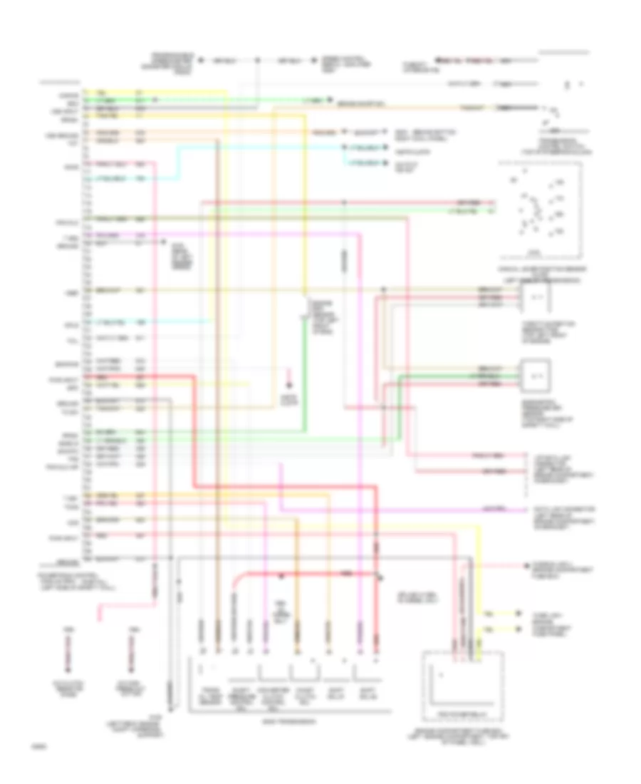
7.3L Diesel, Transmission Wiring Diagram for Ford Pickup F250 1994
List of elements for 7.3L Diesel, Transmission Wiring Diagram for Ford Pickup F250 1994:
- (behind bottom
- (left engine compartment, top frt
- (left front engine
- (left rear of engine compartment, on bracket)
- (left side of safety wall)
- (left side of transmission)
- (mlps)
- (partial)
- (psom)
- (top of steering column)
- 4x4 hi/lo ind sw
- A/c clutch
- A/c high press cut
- Accs
- Baro s
- Barometric pressure (bp) sensor (top right side of safety wall)
- Boo
- Brake on/off sw
- Ccs
- Coast clutch sol
- Compartment fuse panel)
- Compt upper rad
- Converter clutch control sol
- Data link connector
- Diesel only
- Diode
- E40d transmission
- Elect pressure control sol
- Engine compartment fuse box
- Engine rpm sensor (top left front of eng)
- Epc
- Epcpwr
- Fuse #17 (interior f/b)
- Fuse link i (engine
- Fusible link u (engine compartment fuse box)
- G100 (rear of left fender apron)
- G108
- G203 right cowl panel)
- Ground
- Idi
- Instr clstr
- Kapwr
- Manual lever position sensor
- Module (pcm)
- Mpls
- Nca
- Odometer module
- Of wheel well)
- Off
- Out sw
- Pcm dlc
- Pcm dlc inp
- Pcm power relay
- Powertrain control
- Programmable speedometer/
- Pwr input
- Red
- Resistor
- Rpms+
- Rpms-
- Shift sol #1
- Shift sol #2
- Sig rtn
- Speed control servo / amplifier assy
- Splice w/1994 idi diesel only
- Support)
- T ss1
- T ss2
- Tc sw
- Tccs
- Tcil
- Throttle position sensor (tps) (top left front of engine)
- Tot
- Tps
- Trans oil temp sensor
- Transmission control switch
- Vip data link connector (left rear of engine compartment, on bracket)
- Vref
- Vss ground
- Vss input
Transfer Case Wiring Diagram for Ford Pickup F250 1994
List of elements for Transfer Case Wiring Diagram for Ford Pickup F250 1994:
- (below vehicle on front of transfer case)
- (fuse
- (left side of transmission)
- * w/ e40d transmission ** w/ 4r70w transmission
- 4x2
- 4x4
- 4x4 hi/low ind sw
- 4x4 ind feed
- 4x4 input
- 5**
- 8**
- C.b. battery feed
- C/b #12 (fuse panel i/p)
- C221
- C222
- C223
- Clutch coil control
- Electronic shift control module (behind right cowl panel)
- Electronic shift control sw (top left side of i/p,
- Fuse #17
- Fuse #18 (fuse panel i/p)
- Fuse 10 (fuse panel i/p)
- Fused acc feed
- G108 (left front engine compartment on upper radiator support))
- G200 (behind bottom of left cowl panel)
- G203 (behind bottom of right cowl panel)
- Gas engine w/ shift on the fly
- Ground
- Illum
- Instr cluster
- Logic ground
- Low
- Low range indicator feed
- Low range input
- Magnetic clutch coil
- Manual lever position sensor
- Mtr control ccw
- Mtr control cw
- Neutral start sw
- Panel i/p)
- Rear anti- lock brake module
- Red/
- Right side of cluster)
- Sensor
- Shift ctrl sw feed
- Shift motor
- Shift position
- Speed sens feed
- Speed sens return
- Speed sensor
- Transfer case assembly
7.5L
7.5L, Transmission Wiring Diagram for Ford Pickup F250 1994
List of elements for 7.5L, Transmission Wiring Diagram for Ford Pickup F250 1994:
- gnd
- (1993 models) a/c clutch diode (1994 models)
- (1994 models)
- (4.9l-right front of engine, near intake runner #1)
- (5.0l & 5.8l-top center front of engine, near intake runner #6)
- (7.5l-top center of engine, behind distributor)
- (behind bottom of right cowl panel)
- (engine compartment
- (except 7.5l-center front of engine, on thermostat housing)
- (left rear of engine compartment, on bracket)
- (left side of safety wall)
- (rear of left fender apron)
- (top of engine, on throttle body)
- (tps pigtail used on all models except 4.9l)
- 1993 m0dels (4.9l,5.0l,5.8l,5.8l lightning & 7.5l w/ e4od transmission)
- 1994 m0dels (4.9l,5.8l & 7.5l w/ e40d transmission)
- 4.9l
- 4x4 hi/low ind sw
- 4x4 ind
- A/c clutch resistor diode
- A/c high pressure cut out switch
- Accs
- All models except lightning
- Assembly
- Boo
- Brake on/off switch
- Ccs
- Ckp
- Coast clutch sol
- Column)
- Compartment, on
- Distributor
- Dlc
- E40d transmission
- Ect
- Egr valve position sensor
- Elect pressure control sol
- Engine compartment fuse box (left side of engine compartment, top front of wheel well)
- Engine coolant temperature sensor (7.5l-left front of engine, left side of distributor)
- Epc
- Except
- Except 4.9l
- Fuel injectors & engine solenoids
- Fuel pump relay
- Fuse #17 (fuse
- Fuse box)
- Fusible link cartridge i
- Fusible link cartridge i (engine compartment
- Fusible link cartridge u (engine compartment
- G101 (right front of engine compartment, front of fender apron)
- G104
- G108 (left front of engine
- G203
- Gnd
- Iat
- Ign
- Ign
- Ignition control module
- Inst clstr
- Intake air temperature sensor
- Kapwr
- Malfunction ind lp (inst clstr)
- Manifold absolute pressure sensor (top right side of safety wall)
- Manual lever position sensor (left side of transmission)
- Map
- Mil feed
- Mlp
- Nca
- Off
- Panel)
- Pcm power diode
- Pcm power relay
- Powertrain control module (pcm) (partial)
- Programmable speedometer/ odometer module (inst clstr)
- Red
- Servo/amplifier
- Shift sol #1
- Shift sol #2
- Sig rtn
- Speed control
- Ss1
- Ss2
- Support)
- Tcc
- Tcil
- Tcs
- Tft
- Throttle position sensor
- Torque converter clutch sol
- Trans oil temp sensor
- Transmission control switch (top of steering
- Upper radiator
- Vip data link connector
- Vip data link connector (partial)
- Vip dl input
- Vip dlc
- Vref
- Vss (+)
- Vss (-)
Transfer Case Wiring Diagram for Ford Pickup F250 1994
List of elements for Transfer Case Wiring Diagram for Ford Pickup F250 1994:
- (below vehicle on front of transfer case)
- (fuse
- (left side of transmission)
- * w/ e40d transmission ** w/ 4r70w transmission
- 4x2
- 4x4
- 4x4 hi/low ind sw
- 4x4 ind feed
- 4x4 input
- 5**
- 8**
- C.b. battery feed
- C/b #12 (fuse panel i/p)
- C221
- C222
- C223
- Clutch coil control
- Electronic shift control module (behind right cowl panel)
- Electronic shift control sw (top left side of i/p,
- Fuse #17
- Fuse #18 (fuse panel i/p)
- Fuse 10 (fuse panel i/p)
- Fused acc feed
- G108 (left front engine compartment on upper radiator support))
- G200 (behind bottom of left cowl panel)
- G203 (behind bottom of right cowl panel)
- Gas engine w/ shift on the fly
- Ground
- Illum
- Instr cluster
- Logic ground
- Low
- Low range indicator feed
- Low range input
- Magnetic clutch coil
- Manual lever position sensor
- Mtr control ccw
- Mtr control cw
- Neutral start sw
- Panel i/p)
- Rear anti- lock brake module
- Red/
- Right side of cluster)
- Sensor
- Shift ctrl sw feed
- Shift motor
- Shift position
- Speed sens feed
- Speed sens return
- Speed sensor
- Transfer case assembly