AIR CONDITIONING
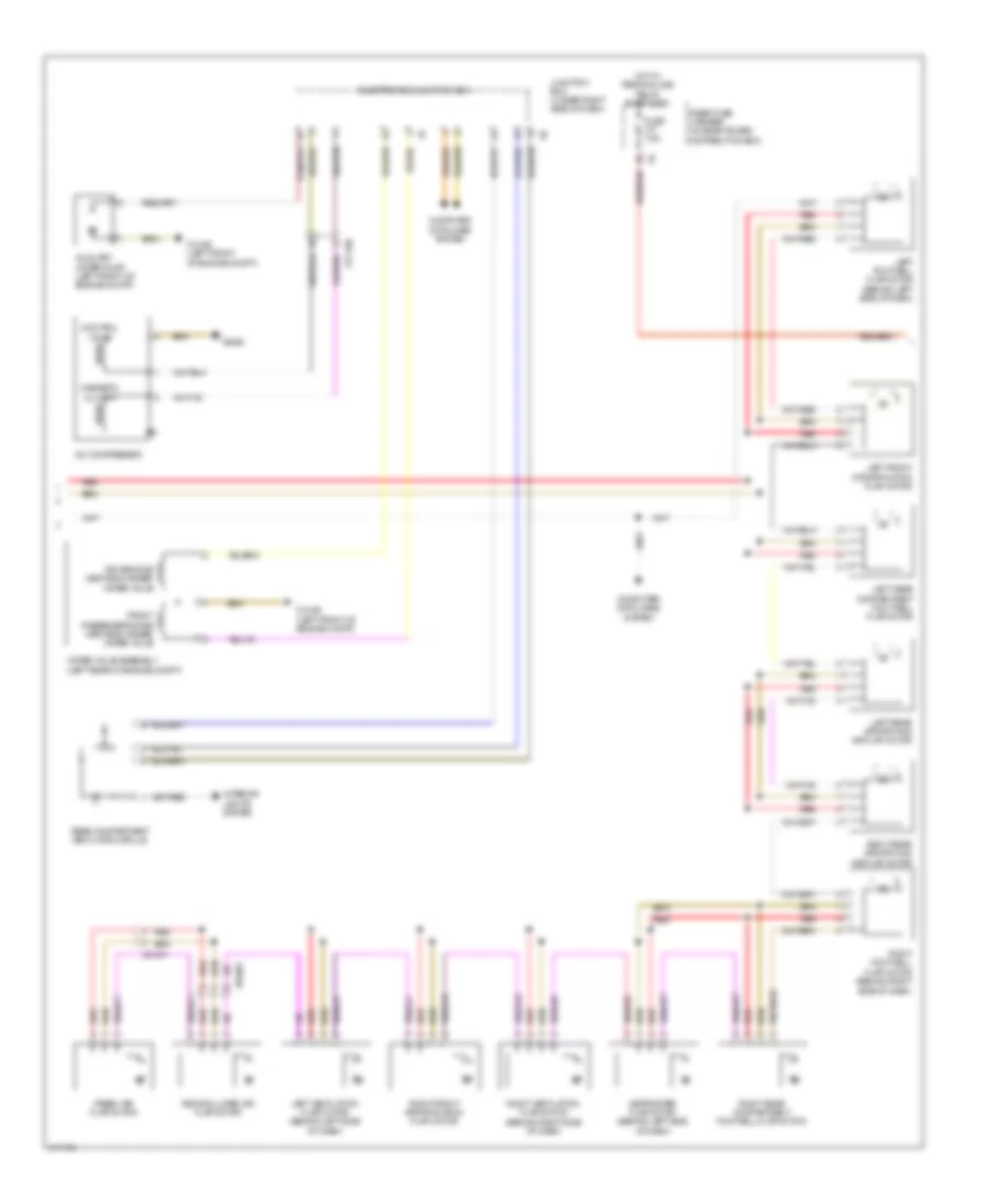
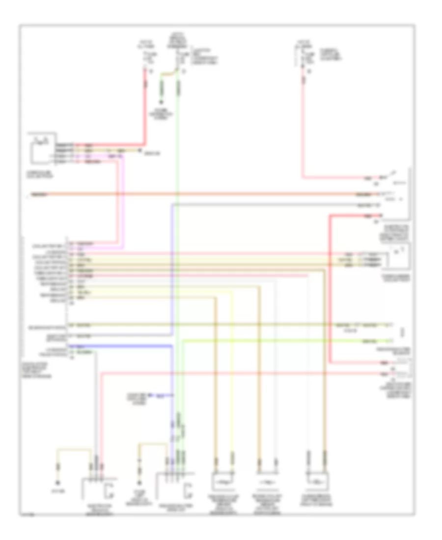
Automatic A/C Wiring Diagram, with Rear Compartment Blower (1 of 3) for BMW 650i Gran Coupe 2013

List of elements for Automatic A/C Wiring Diagram, with Rear Compartment Blower (1 of 3) for BMW 650i Gran Coupe 2013:
- 13b
- Activation ioniser
- Auc sensor
- Blower motor (under right side of dash)
- Blower output stage (on blower motor)
- Body can bus sig
- Computer data lines system
- Electronics junction box
- Evaporator temperature sensor (on a/c evaporator)
- Front center ventilation grille
- Fuse 40a
- Fuse 5a
- Fuse 7.5a
- Gnd
- Gnd ioniser
- Heating/air conditioning system (center of dash)
- Hot at all times
- Hot w/ bistable relay energized
- Hot w/ terminal 15n relay energized
- Interior lights system
- Ionizer (on hvac unit)
- Junction box (under right side of dash)
- Left adjuster sig
- Left front ventilation temperature sensor
- Left heat exchanger temperature sensor (behind center of dash)
- Left stratification actuator
- Lin bus sig
- Locator lighting
- N2 1b
- Nca
- Power distribution system
- Red
- Refrigerant pressure sensor (right front wheelwell)
- Right front ventilation temperature sensor
- Right heat exchanger temperature sensor (behind center of dash)
- Sens gnd
- Sens sig
- Sig evaporator temp sens
- Sply volt
- Temp sens
- Z10 11b (right kick panel)
- Z10 6b (late production) z10 3b (early production) (late production: right kick panel) (early production: right front of engine compt)
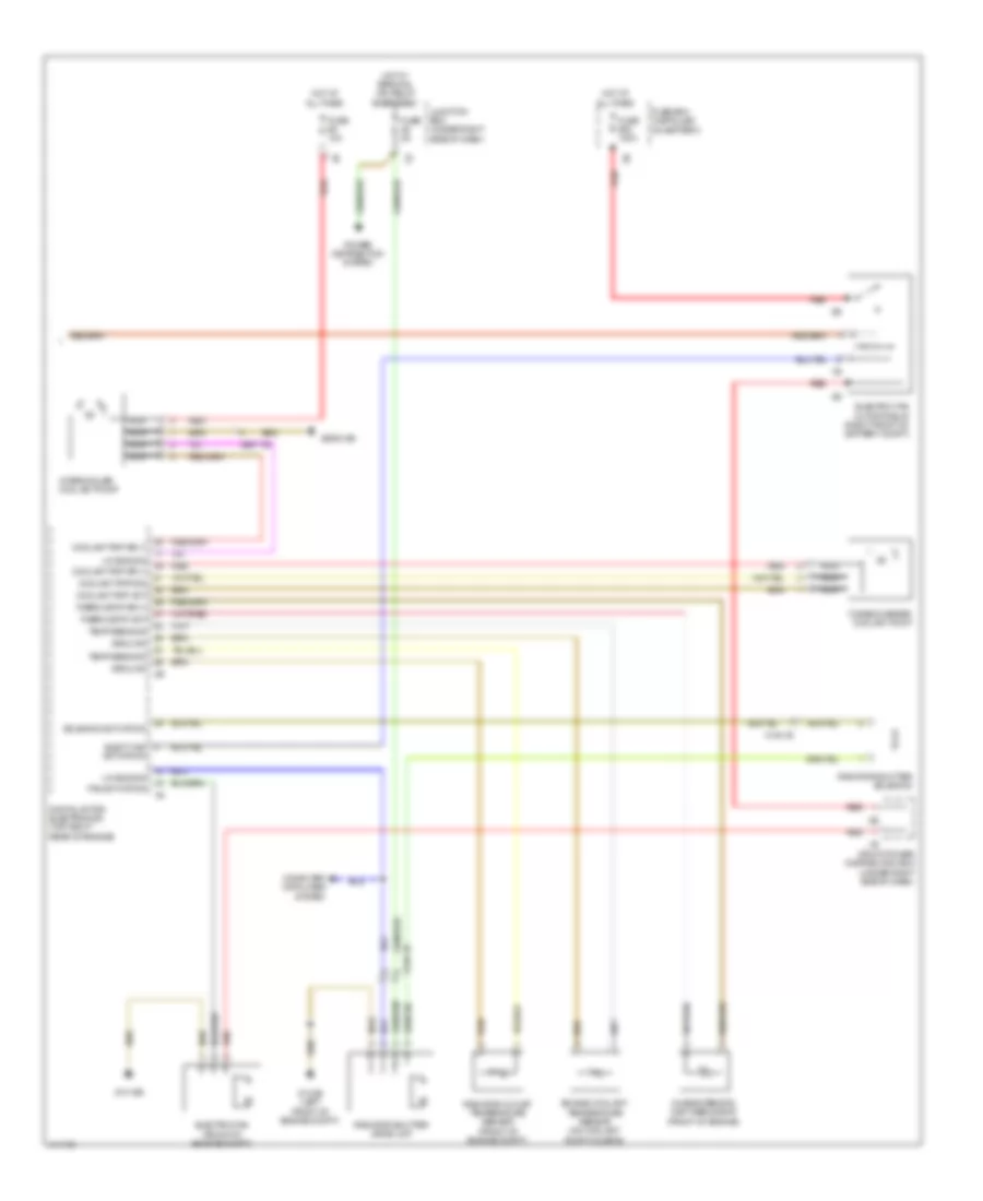
Automatic A/C Wiring Diagram, with Rear Compartment Blower (2 of 3) for BMW 650i Gran Coupe 2013
List of elements for Automatic A/C Wiring Diagram, with Rear Compartment Blower (2 of 3) for BMW 650i Gran Coupe 2013:
- A/c compressor
- Auxiliary water pump (left front of engine compt)
- Computer data lines system
- Control valve
- Defroster flap motor (behind left side of dash)
- Driver side heat exchanger water valve
- Electronics junction box
- Fresh air flap motor
- Front passenger's side heat exchanger water valve
- Fuse 7.5a
- Hot w/ terminal 30b relay energized
- Interior lights system
- Junction box (under right side of dash)
- Left footwell flap motor (behind left side of dash)
- Left front stratification flap motor
- Left rear compartment footwell flap motor
- Left rear stratifying air flap motor
- Left ventilation flap motor (behind left side of dash)
- Magnetic clutch
- Rear compartment ventilation grille
- Rear fuse carrier (in rear power distribution box)
- Recirculated air flap motor
- Red
- Right footwell flap motor (behind right side of dash)
- Right front stratification flap motor
- Right rear compartment footwell flap motor
- Right rear stratifying air flap motor
- Right ventilation flap motor (behind right side of dash)
- Water valve assembly (left rear of engine compt)
- X01001
- X13 10b
- X6460
- Z10 2b (left front of engine compt)
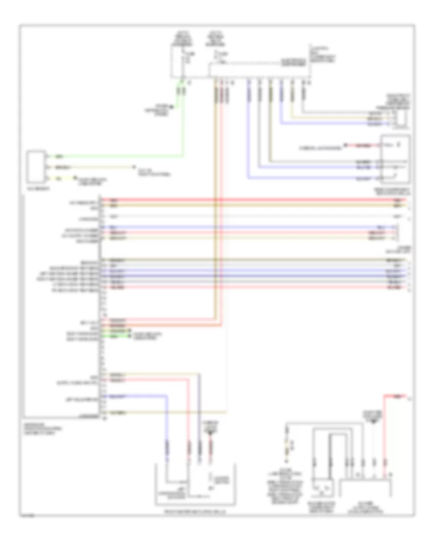
Automatic A/C Wiring Diagram, with Rear Compartment Blower (3 of 3) for BMW 650i Gran Coupe 2013
List of elements for Automatic A/C Wiring Diagram, with Rear Compartment Blower (3 of 3) for BMW 650i Gran Coupe 2013:
- Activation
- Characteristic map thermostat (front of engine)
- Computer data lines system
- Coolant pmp act
- Coolant pmp sig
- Coolant pmp sply
- Digital motor electronics (top right rear of engine)
- Elect fan
- Electric fan (front of engine compt)
- Electric fan cutoff relay (right front of battery compt)
- Engine coolant temperature sensor (on coolant pump housing)
- Fan activation
- Front power distribution box (under right side of dash)
- Fuse 100a
- Fuse 10a
- Fuse 5a
- Fuse box (installed on battery)
- Ground
- Hot at all times
- Hot w/ terminal 15n relay energized
- Intercooler coolant pump
- Junction box (under right side of dash)
- Lin bus sig
- Nca
- Power distribution system
- Radiator outlet temperature sensor (front of engine compt)
- Radiator shutter drive unit
- Radiator shutter solenoid
- Red
- Solenoid activation
- Temp sens sig
- Thermostat act
- Thermostat sply
- Turbocharger coolant pump
- X148 1b
- X697 1b
- Z10 15b
- Z10 2b (left front of engine compt)
- Z6000 5b
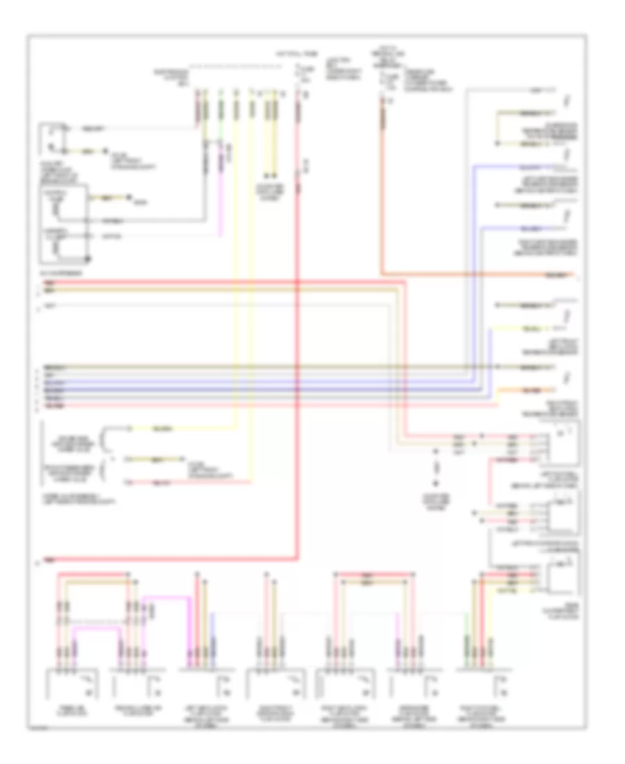
Automatic A/C Wiring Diagram, without Rear Compartment Blower (1 of 3) for BMW 650i Gran Coupe 2013
List of elements for Automatic A/C Wiring Diagram, without Rear Compartment Blower (1 of 3) for BMW 650i Gran Coupe 2013:
- (right front wheelwell) refrigerant pressure sensor
- Activation ioniser
- Auc sensor
- Blower motor (under right side of dash)
- Blower output stage (on blower motor)
- Body can bus sig
- Computer data lines system
- Electronics junction box
- Front center ventilation grille
- Fuse 5a
- Fuse 7.5a
- Gnd
- Gnd ioniser
- Heating/air conditioning system (center of dash)
- Hot w/ bistable relay energized
- Hot w/ terminal 15n relay energized
- Interior lights system
- Ionizer (on hvac unit)
- Junction box (under right side of dash)
- Left adjuster sig
- Left heat exchanger temp sens
- Left stratification actuator
- Lf ventilation temp sens
- Lin bus sig
- Locator lighting
- N2 1b
- Nca
- Power distribution system
- Rear compartment ventilation grille
- Red
- Rf ventilation temp sens
- Right heat exchanger temp sens
- Sens gnd
- Sig evaporator temp sens
- Sply volt
- Z10 11b (right kick panel)
- Z10 6b (late production) z10 3b (early production) (late production: right kick panel) (early production: right front of engine compt)
Automatic A/C Wiring Diagram, without Rear Compartment Blower (2 of 3) for BMW 650i Gran Coupe 2013
List of elements for Automatic A/C Wiring Diagram, without Rear Compartment Blower (2 of 3) for BMW 650i Gran Coupe 2013:
- 13b
- A/c compressor
- Auxiliary water pump (left front of engine compt)
- Computer data lines system
- Control valve
- Defroster flap motor (behind left side of dash)
- Driver side heat exchanger water valve
- Electronics junction box
- Evaporator temperature sensor (on a/c evaporator)
- Fresh air flap motor
- Front passenger's heat exchanger water valve
- Fuse 40a
- Fuse 7.5a
- Hot at all times
- Hot w/ terminal 30b relay energized
- Junction box (under right side of dash)
- Left footwell flap motor (behind left side of dash)
- Left front stratification flap motor
- Left front ventilation temperature sensor
- Left heat exchanger temperature sensor (behind center of dash)
- Left ventilation flap motor (behind left side of dash)
- Magnetic clutch
- N2 1b
- Rear compartment flap motor
- Rear fuse carrier (in rear power distribution box)
- Recirculated air flap motor
- Red
- Right footwell flap motor (behind right side of dash)
- Right front stratification flap motor
- Right front ventilation temperature sensor
- Right heat exchanger temperature sensor (behind center of dash)
- Right ventilation flap motor (behind right side of dash)
- Water valve assembly (left rear of engine compt)
- X01001
- X13 10b
- X6460
- Z10 2b (left front of engine compt)
Automatic A/C Wiring Diagram, without Rear Compartment Blower (3 of 3) for BMW 650i Gran Coupe 2013
List of elements for Automatic A/C Wiring Diagram, without Rear Compartment Blower (3 of 3) for BMW 650i Gran Coupe 2013:
- Activation
- Characteristic map thermostat (front of engine)
- Computer data lines system
- Coolant pmp act
- Coolant pmp sig
- Coolant pmp sply
- Digital motor electronics (top right rear of engine)
- Elect fan
- Electric fan (front of engine compt)
- Electric fan cutoff relay (right front of battery compt)
- Engine coolant temperature sensor (on coolant pump housing)
- Fan activation
- Front power distribution box (under right side of dash)
- Fuse 100a
- Fuse 10a
- Fuse 5a
- Fuse box (installed on battery)
- Ground
- Hot at all times
- Hot w/ terminal 15n relay energized
- Intercooler coolant pump
- Junction box (under right side of dash)
- Lin bus sig
- Nca
- Power distribution system
- Radiator outlet temperature sensor (front of engine compt)
- Radiator shutter drive unit
- Radiator shutter solenoid
- Red
- Solenoid activation
- Temp sens sig
- Thermostat act
- Thermostat sply
- Turbocharger coolant pump
- X148 1b
- X697 1b
- Z10 15b
- Z10 2b (left front of engine compt)
- Z6000 5b
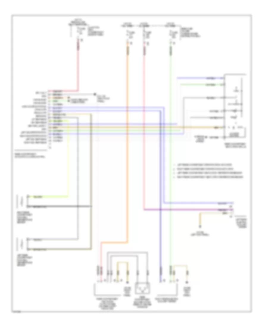
Rear Heater & A/C Wiring Diagram for BMW 650i Gran Coupe 2013
List of elements for Rear Heater & A/C Wiring Diagram for BMW 650i Gran Coupe 2013:
- 12b
- 4-dr coupé activation
- Can bus sig
- Computer data lines system
- Fuse 20a
- Fuse 30a
- Fuse 5a
- Gnd
- Hot at all times
- Hot w/ terminal 30b relay energized
- Interior lights system
- Junction box (under right side of dash)
- Left rear compartment footwell temperature sensor
- Left rear compartment stratification actuator
- Left rear compartment ventilation temperature sensor
- Left rear electric auxiliary heater
- Left sig stratification
- Left sig temp sens
- Locator lighting
- Lr aux htr
- Lr temp sens
- Nca
- Rear compartment automatic climate control
- Rear compartment blower motor (rear of center console)
- Rear compartment fan motor output stage (on rear compt fan motor)
- Rear compartment ventilation grille
- Rear fuse holder (in rear power distribution box)
- Right rear compartment footwell temperature sensor
- Right rear compartment stratification actuator
- Right rear compartment ventilation temperature sensor
- Right rear electric auxiliary heater
- Right sig stratification
- Right sig temp sens
- Rr aux htr
- Rr temp sens
- Sens gnd
- Sply volt
- Vent grille sply
- Z10 11b (right kick panel)
- Z10 5b (left kick panel)
- Z10 6b (right kick panel)