POWER DISTRIBUTION
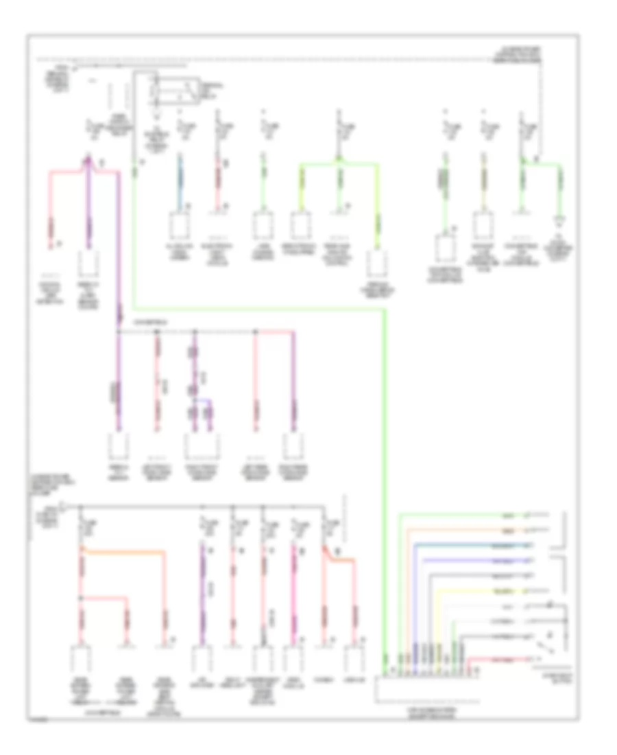
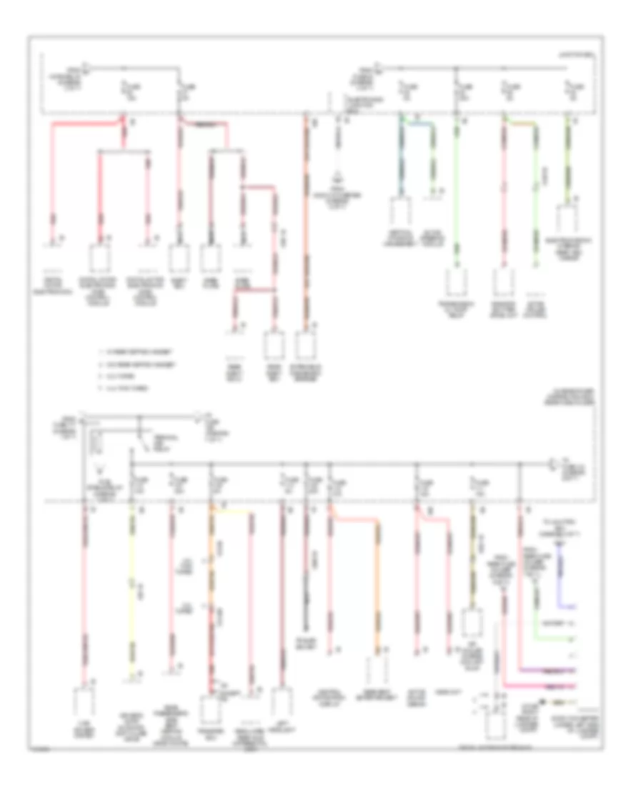
Power Distribution Wiring Diagram (1 of 7) for BMW 650i Gran Coupe 2013

List of elements for Power Distribution Wiring Diagram (1 of 7) for BMW 650i Gran Coupe 2013:
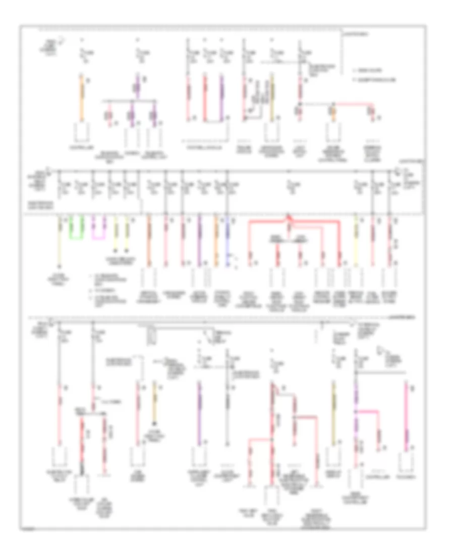
Power Distribution Wiring Diagram (2 of 7) for BMW 650i Gran Coupe 2013
List of elements for Power Distribution Wiring Diagram (2 of 7) for BMW 650i Gran Coupe 2013:
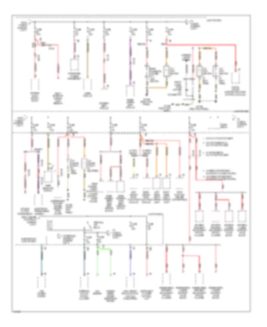
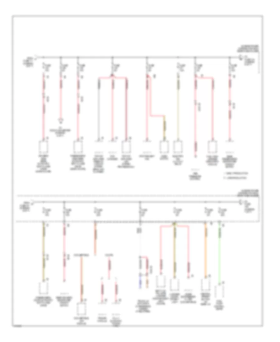
Power Distribution Wiring Diagram (3 of 7) for BMW 650i Gran Coupe 2013
List of elements for Power Distribution Wiring Diagram (3 of 7) for BMW 650i Gran Coupe 2013:
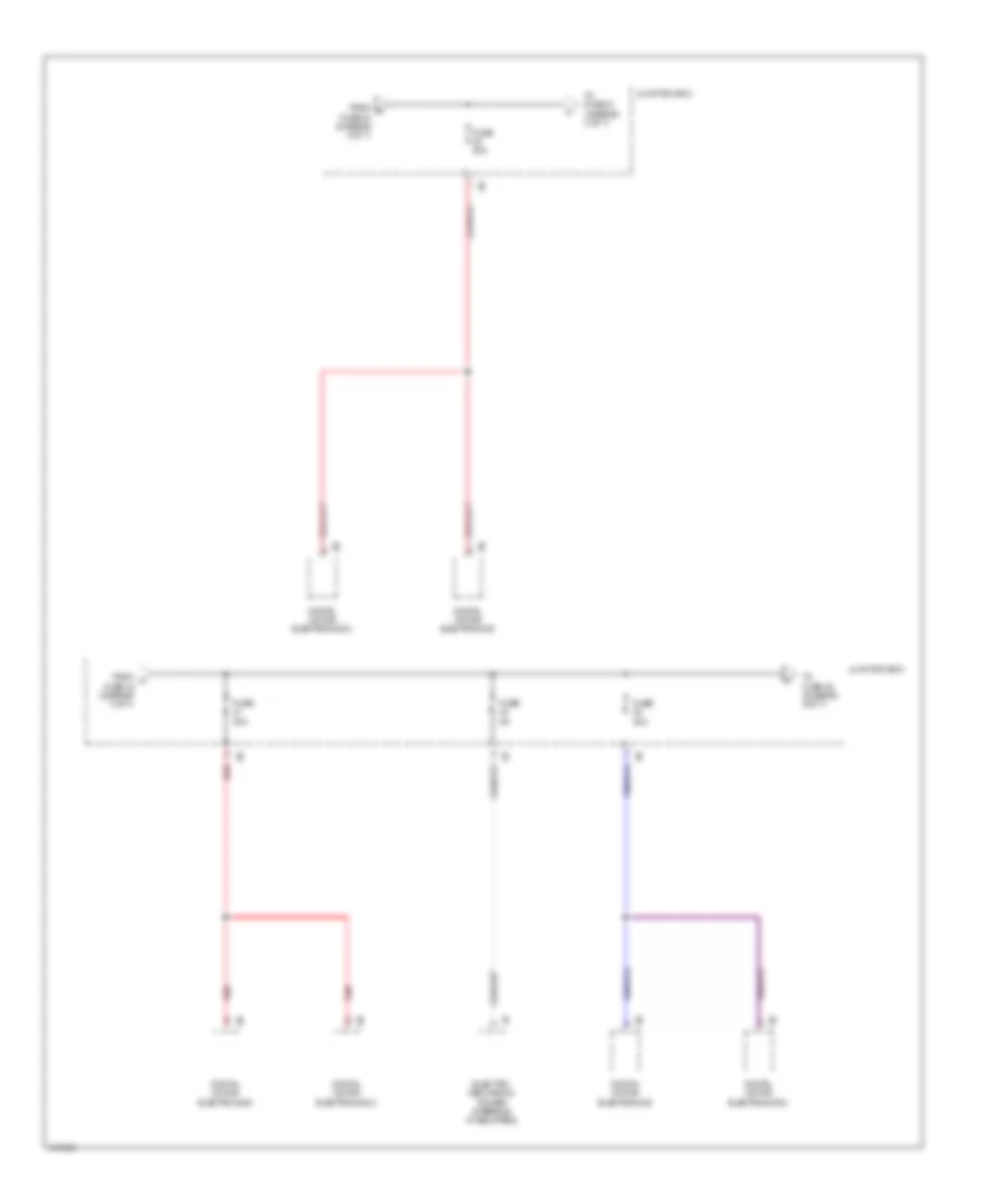
Power Distribution Wiring Diagram (4 of 7) for BMW 650i Gran Coupe 2013
List of elements for Power Distribution Wiring Diagram (4 of 7) for BMW 650i Gran Coupe 2013:
Power Distribution Wiring Diagram (5 of 7) for BMW 650i Gran Coupe 2013
List of elements for Power Distribution Wiring Diagram (5 of 7) for BMW 650i Gran Coupe 2013:
Power Distribution Wiring Diagram (6 of 7) for BMW 650i Gran Coupe 2013
List of elements for Power Distribution Wiring Diagram (6 of 7) for BMW 650i Gran Coupe 2013:
Power Distribution Wiring Diagram (7 of 7) for BMW 650i Gran Coupe 2013
List of elements for Power Distribution Wiring Diagram (7 of 7) for BMW 650i Gran Coupe 2013: