ENGINE PERFORMANCE
4.4L TWIN TURBO
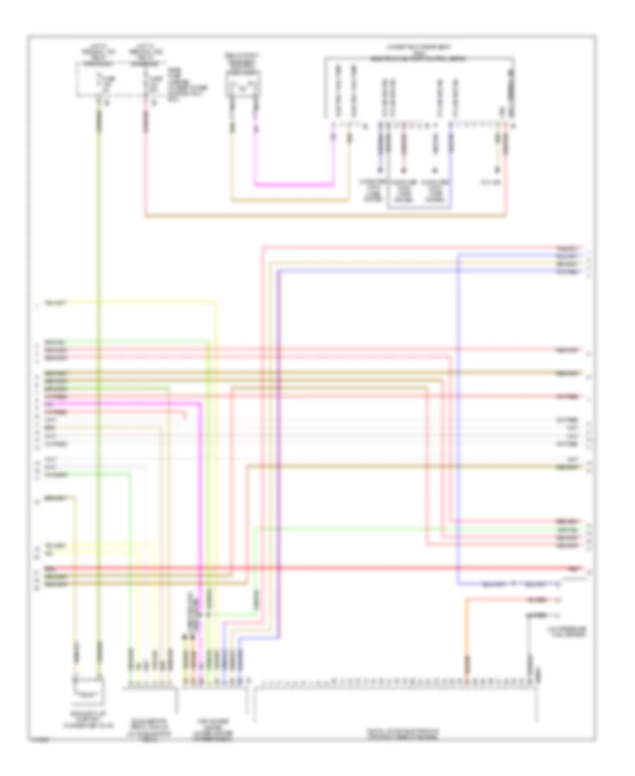
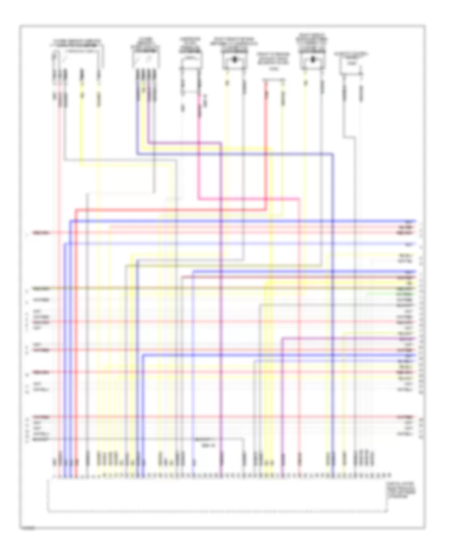
4.4L Twin Turbo, Engine Performance Wiring Diagram (1 of 11) for BMW 650i Gran Coupe 2013

List of elements for 4.4L Twin Turbo, Engine Performance Wiring Diagram (1 of 11) for BMW 650i Gran Coupe 2013:
- (top right side of fuel tank) natural vacuum leak detection
- 11b
- Car access system (under center of rear shelf)
- Clutch module (m/t) (on clutch master cylinder)
- Computer data lines system
- Cooling fans system
- Dc/dc converter (under left side of luggage compt)
- Digital motor electronics (top right rear of engine)
- Fuse 15a
- Fuse 5a
- Hot at all times
- Hot w/ terminal 30b relay energized
- Ignition coils cylinder (ignition coils 1, 2, 3 & 4: on right cylinder bank) (ignition coils 5 & 6: on left cylinder bank)
- Junction box
- Nca
- Power distribution system
- Pressure switch
- Rear fuse holder
- Red
- Spark plug
- Z10 13b (right "c" pillar)
- Z10 9b (left kick panel)
- Z6000 1b
- Z6000 2b
- Z6000 3b
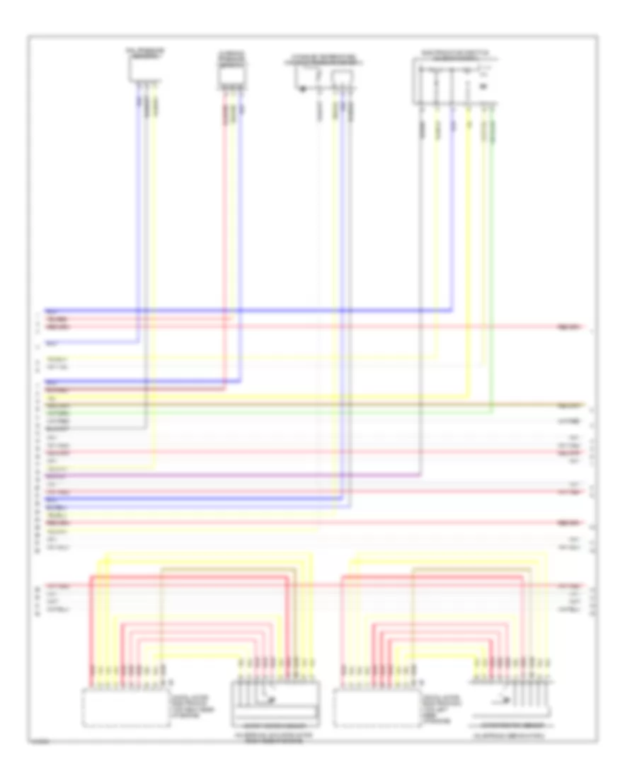
4.4L Twin Turbo, Engine Performance Wiring Diagram (2 of 11) for BMW 650i Gran Coupe 2013
List of elements for 4.4L Twin Turbo, Engine Performance Wiring Diagram (2 of 11) for BMW 650i Gran Coupe 2013:
- (at accelerator pedal)
- (below right rear seat) electric fuel pump
- (under right rear seat) (650i) electric fuel pump control (ekps)
- Accelerator pedal module
- Car access system (under center of rear shelf)
- Computer data lines system
- Digital motor electronics (top right rear of engine)
- Electric fuel pump
- Exhaust flap electric changeover valve
- Fuse 20a
- Fuse 5a
- Gnd
- Hot w/ terminal 15n relay energized
- Hot w/ terminal 30b relay energized
- Lines system computer data
- Low pressure fuel sensor
- Nca
- Pt-can bus sig
- Rear fuse carrier (in rear power distribution box)
- Red
- Sply, terminal 30b
- X60004
- Z10 18b
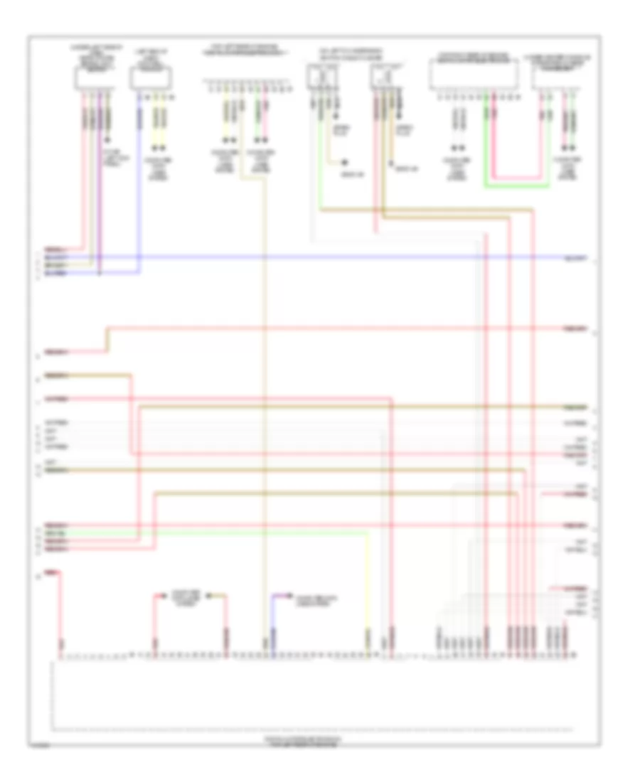
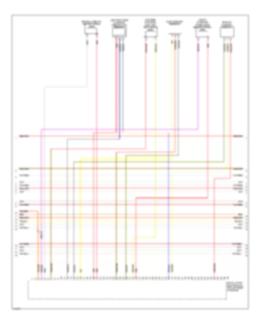
4.4L Twin Turbo, Engine Performance Wiring Diagram (3 of 11) for BMW 650i Gran Coupe 2013
List of elements for 4.4L Twin Turbo, Engine Performance Wiring Diagram (3 of 11) for BMW 650i Gran Coupe 2013:
- (left end of dash) footwell module
- (on left cylinder bank)
- (top left rear of engine) digital motor electronics 2
- (top right rear of engine) digital motor electronics
- (under center console) integrated chassis management
- (under left side of dash) (gran coupe) brake light switch
- Computer data lines system
- Digital motor electronics 2 (top left rear of engine)
- Ignition coils cylinder
- Nca
- Pnk
- Red
- Spark plug
- Z10 9b (left kick panel)
- Z6000 4b
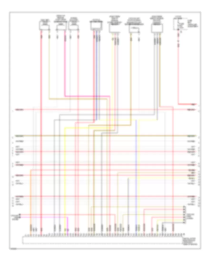
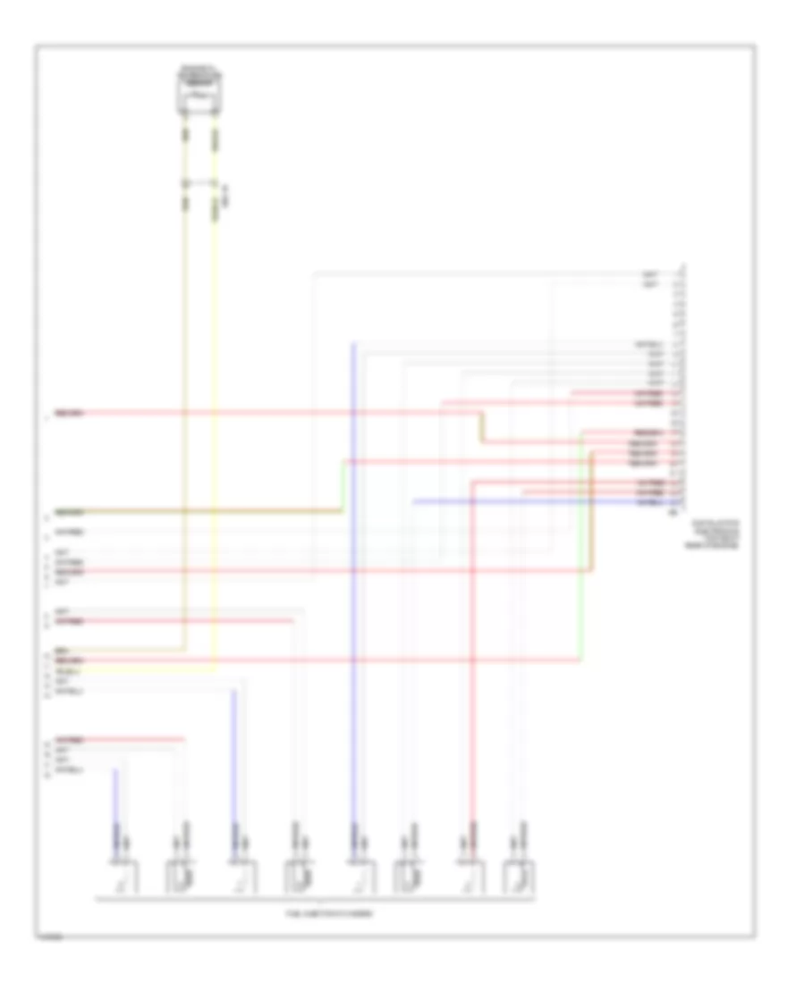
4.4L Twin Turbo, Engine Performance Wiring Diagram (4 of 11) for BMW 650i Gran Coupe 2013
List of elements for 4.4L Twin Turbo, Engine Performance Wiring Diagram (4 of 11) for BMW 650i Gran Coupe 2013:
- (end of fuel-distribution rail) rail pressure sensor
- (in exhaust, downstream of catalytic converter) oxygen sensor after catalytic converter
- (left side of engine) oil pressure switch
- (on exhaust manifold) oxygen sensor before catalytic converter
- (right side of engine, between cylinders 1 & 2) cylinder 1 & 2 knock sensor
- (right side of engine, between cylinders 3 & 4) cylinder 3 & 4 knock sensor
- Digital motor electronics (top right rear of engine)
- Nca
- Oil level sensor
- Quantity control valve
- Red
- Starting/ charging system
- Wastegate valve pressure converter
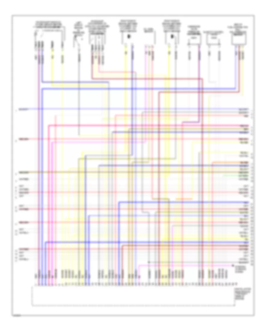
4.4L Twin Turbo, Engine Performance Wiring Diagram (5 of 11) for BMW 650i Gran Coupe 2013
List of elements for 4.4L Twin Turbo, Engine Performance Wiring Diagram (5 of 11) for BMW 650i Gran Coupe 2013:
- (front of engine) exhaust vanos solenoid valve
- (front of intake manifold) intake air temperature/ manifold pressure sensor
- (lower front of engine) crankshaft sensor
- (on manual transmission) (m/t) zero gear sensor
- (on throttle body) electromotive throttle actuator
- Charging pressure sensor
- Digital motor electronics (top right rear of engine)
- Red
- X60004
- X697 1b
4.4L Twin Turbo, Engine Performance Wiring Diagram (6 of 11) for BMW 650i Gran Coupe 2013
List of elements for 4.4L Twin Turbo, Engine Performance Wiring Diagram (6 of 11) for BMW 650i Gran Coupe 2013:
- (front of engine) exhaust vanos solenoid valve 2
- (right side of engine, between cylinders 5 & 6) cylinder 5 & 6 knock sensor
- (right side of engine, between cylinders 7 & 8) cylinder 7 & 8 knock sensor
- Digital motor electronics 2 (top left rear of engine)
- Nca
- Oxygen sensor 2 after catalytic converter
- Oxygen sensor 2 before catalytic converter
- Quantity control valve 2
- Red
- Wastegate valve 2 pressure converter
- X698 1b
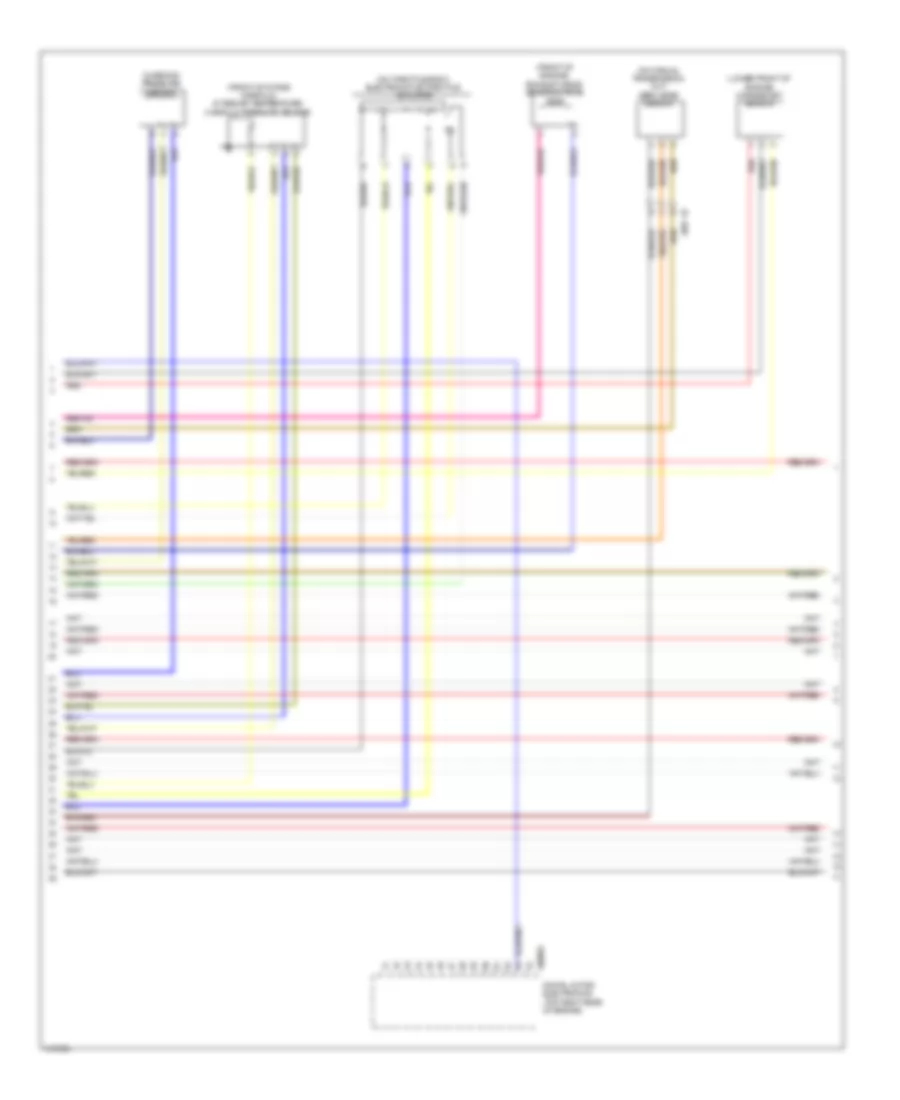
4.4L Twin Turbo, Engine Performance Wiring Diagram (7 of 11) for BMW 650i Gran Coupe 2013
List of elements for 4.4L Twin Turbo, Engine Performance Wiring Diagram (7 of 11) for BMW 650i Gran Coupe 2013:
- Charging pressure sensor 2
- Digital motor electronics (top right rear of engine)
- Digital motor electronics 2 (top left rear of engine)
- Electromotive throttle valve actuator 2
- Intake air temperature/ manifold pressure sensor 2
- Motor position sensor
- Rail pressure sensor 2
- Red
- Valvetronic actuator motor (right side of engine)
- Valvetronic servomotor 2
4.4L Twin Turbo, Engine Performance Wiring Diagram (8 of 11) for BMW 650i Gran Coupe 2013
List of elements for 4.4L Twin Turbo, Engine Performance Wiring Diagram (8 of 11) for BMW 650i Gran Coupe 2013:
- (front of engine) inlet vanos solenoid valve
- (on coolant pump housing) engine coolant temperature sensor
- (right rear side of engine) exhaust camshaft sensor
- (right rear side of engine) intake camshaft sensor
- Bypass blow-off valve
- Cooling fans system
- Digital motor electronics (top right rear of engine)
- Fuse 100a
- Fuse box (installed on battery)
- Hot at all times
- Hot film air mass meter
- Red
- Tank vent valve
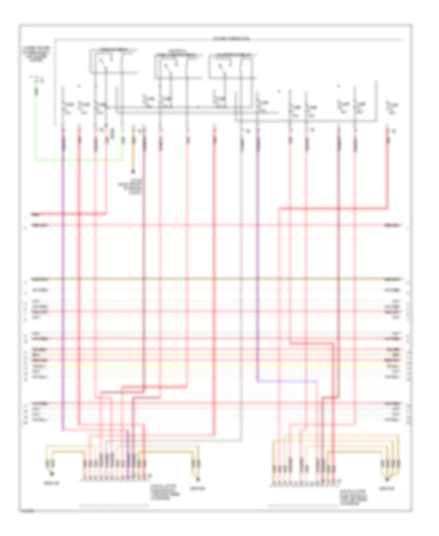
4.4L Twin Turbo, Engine Performance Wiring Diagram (9 of 11) for BMW 650i Gran Coupe 2013
List of elements for 4.4L Twin Turbo, Engine Performance Wiring Diagram (9 of 11) for BMW 650i Gran Coupe 2013:
- (under center of rear shelf) car access system
- Digital motor electronics (top right rear of engine)
- Digital motor electronics 2 (top left rear of engine)
- Dme main relay
- Fuse 10a
- Fuse 15a
- Fuse 20a
- Fuse 40a
- Ignition & fuel injection relay
- Power distribution
- Red
- Valvetronic relay
- X60189
- Z10 3b (right front of engine compt)
- Z6000 5b
- Z6000 6b
4.4L Twin Turbo, Engine Performance Wiring Diagram (10 of 11) for BMW 650i Gran Coupe 2013
List of elements for 4.4L Twin Turbo, Engine Performance Wiring Diagram (10 of 11) for BMW 650i Gran Coupe 2013:
- (front of engine) intake vanos solenoid valve 2
- (left front side of engine) mass air flow sensor 2
- (top rear of engine) fuel tank vent valve 2
- Digital motor electronics 2 (top left rear of engine)
- Exhaust camshaft sensor 2
- Inlet camshaft sensor 2
- Recirculated air control valve 2
- Red
- X698 1b
4.4L Twin Turbo, Engine Performance Wiring Diagram (11 of 11) for BMW 650i Gran Coupe 2013
List of elements for 4.4L Twin Turbo, Engine Performance Wiring Diagram (11 of 11) for BMW 650i Gran Coupe 2013:
- Digital motor electronics (top right rear of engine)
- Engine oil temperature sensor
- Fuel injection cylinders
- X704 1b