COOLING FAN
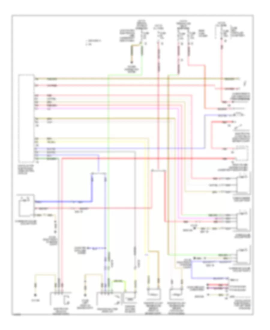
Cooling Fan Wiring Diagram for BMW 650i Gran Coupe 2013
List of elements for Cooling Fan Wiring Diagram for BMW 650i Gran Coupe 2013:
- (or red)
- (right front of engine compt)
- 650i & 650 xi
- Characteristic map thermostat (front of engine)
- Charge air cooler coolant pump
- Charge air cooler coolant pump 2
- Computer data lines system
- Digital motor electronics (dme) control module
- Digital motor electronics 2 (top left rear of engine)
- Electric fan (front of engine compt)
- Electric fan cutoff relay (right front of battery compt)
- Engine coolant temperature sensor (on coolant pump housing)
- Front power distribution box (under right side of dash)
- Fuse 100a
- Fuse 10a
- Fuse 15a
- Fuse 5a
- Fuse 7.5a
- Fuse box (installed on battery)
- Gnd
- Hot at all times
- Hot w/ terminal 15n relay energized
- Hot w/ terminal 30b relay energized
- Intercooler coolant pump
- Junction box electronics (jbe) (under right side of dash)
- Nca
- Power distribution system
- Pt-can bus sig
- Pt-can bus sig 1b
- Radiator outlet temperature sensor (front of engine compt)
- Radiator shutter drive unit
- Radiator shutter solenoid
- Rear fuse holder
- Red
- Term 30
- Turbocharger coolant pump
- X13 1b
- X148 1b
- X252 1b
- X697 1b
- Z10 15b
- Z10 2b (left front of engine compt)
- Z10 3b
- Z10 3b (right front of engine compt)
- Z6000 5b
- Z6000 6b
 English