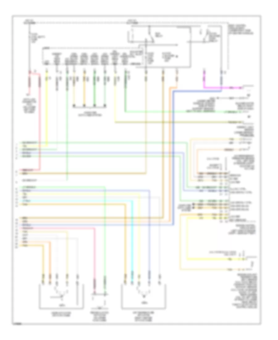
AIR CONDITIONING
Automatic A/C Wiring Diagram (1 of 2) for Chevrolet Malibu LTZ 2008

List of elements for Automatic A/C Wiring Diagram (1 of 2) for Chevrolet Malibu LTZ 2008:
- (2.4l (vin 5)) (3.6l)
- (2.4l: at 4 exhaust port, above cmp exhaust sensor) (3.6l: on trans- mission stud, near pnp switch) g106
- (355 mm from main breakout) (2.4l (vin 5)) j153
- (middle rear of engine) (2.4l (vin 5)) heater coolant pump
- 2.4l (vin b)
- 5 volt ref
- 87a
- A/c clutch fuse 1 10a
- A/c clutch relay
- A/c compressor clutch (front of a/c compressor)
- A/c request ind
- A/c request switch
- A11
- Air temp drv pos sig
- Ambient air temperature sensor (behind grille, on left side of front impact bar)
- Auto
- B10
- Battery positive
- Blower motor switch
- Computer data lines system
- Cool fan 1 fuse 17 30a
- Cool fan 2 fuse 18 30a
- Cool/ fan 1 relay
- Cool/ fan 2 relay
- Cool/fan ser/par relay
- Defog ind
- Defog switch
- Door position sig
- Drv ctrl a
- Drv ctrl b
- Except 2.4l (vin b)
- Fresh air ind
- Fresh air switch
- G106 (2.4l: at 4 exhaust port, above cmp exhaust sensor) (3.6l: on trans- mission stud, near pnp switch)
- G201 (under center console, on right side of front support bracket, next to g203, near bcm)
- Gnd
- High
- Hot at all times
- Hot w/ pwr/trn relay energized
- Hot w/ run/crank relay energized
- Hvac control module (center of dash)
- Ign 3 vol
- Inside duct)
- J151 (2.4l (vin 5)) (305 mm from main breakout) b
- Left engine cooling fan (on front of engine compt)
- Left engine cooling fan diode (2.4l (vin 5)) (between left cooling fan & crankshaft position sensor)
- Logic
- Low
- Low ref
- Lower air temperature sensor (under right console access panel,
- Lower air temperature switch
- Maf injectors bas pmps fuse 5 20a 10a
- Mode drv pos sig
- Mode switch
- Off
- Pnk
- Recir door ctrl
- Recirculation ind
- Recirculation switch
- Req sig
- Right engine cooling fan (on front of engine compt)
- Right engine cooling fan diode (2.4l (vin 5)) (between right cooling fan & a/c compressor breakout)
- S152 (2.4l (vin 5))
- Serial data
- Signal
- Starter generator control module (sgcm) (in left front engine compt, behind headlamp assembly)
- Tan
- To right of bcm)
- Underhood fuse block (on left side of engine compt)
- Upper air temperature sensor (in back of left center a/c vent,
- Upper air temperature switch
Automatic A/C Wiring Diagram (2 of 2) for Chevrolet Malibu LTZ 2008
List of elements for Automatic A/C Wiring Diagram (2 of 2) for Chevrolet Malibu LTZ 2008:
- (below right side of dash) blower motor
- 2.4l (vin b)
- 2.4l (vin b) & 2.4l (vin 5) 3.6l (vin 7)
- 5v ref
- A/c refrigerant pressure sensor (3.6l: left side of engine compt, mounted on a/c line)
- Air temperature actuator (right center of hvac case)
- Ambient air temp sens sig
- Battery positive
- Blower motor control module (on rear of hvac case)
- Body control module (bcm) (under right side of center console)
- Clu rly ctrl
- Computer data lines system
- Data link connector (dlc) (on lower left side of dash)
- Drl ambient light sens low ref
- Drl ambient light sens sig
- Drv sunload sens sig
- Ect sens sig
- Engine control module (ecm) (left side of engine compt, near battery)
- Engine coolant temperature (ect) sensor (2.4l (vin 5): below camshaft position exhaust sensor) (2.4l (vin b): on engine block, at left rear corner) (3.6l: on left side of front cylinder head, below throttle actuator control module)
- Except 2.4l (vin b)
- G203 (under center console, on right side of front support bracket, next to g201, near bcm)
- Gnd
- High spd gmlan
- High spd rly ctrl
- High speed gmlan serial data +
- High speed gmlan serial data -
- Hot at all times
- Hvac ctrl (batt) fuse 10a
- Hvac ctrl (ign) fuse 10a
- Logic
- Low ref
- Low spd rly ctrl
- Low speed gmlan serial data
- Mode actuator (on hvac case)
- Pass sunload sens sig
- Recirculation actuator (on upper hvac case)
- Req sig
- Run relay
- Run rly ctrl
- Sens sig
- Spd ctrl
- Sply voltage
- Sunload sensor (center of instrument panel, in defroster deflector)
- Tan
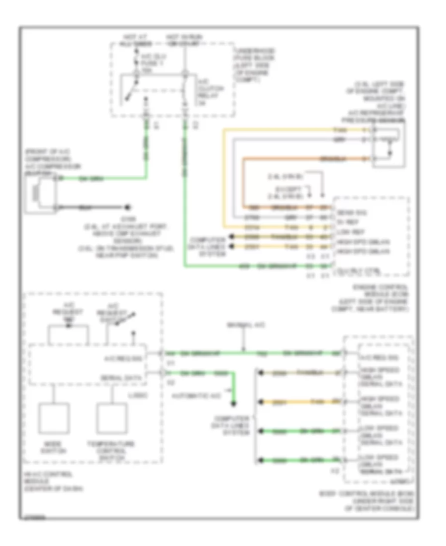
Compressor Wiring Diagram for Chevrolet Malibu LTZ 2008
List of elements for Compressor Wiring Diagram for Chevrolet Malibu LTZ 2008:
- (2.4l: at 4 exhaust port, above cmp exhaust sensor) (3.6l: on transmission stud, near pnp switch)
- (3.6l: left side of engine compt, mounted on a/c line) a/c refrigerant pressure sensor
- (front of a/c compressor) a/c compressor clutch
- 2.4l (vin b)
- 5v ref
- A/c clu fuse 1 10a
- A/c clutch relay
- A/c req sig
- A/c request ind
- A/c request switch
- Automatic a/c
- Body control module (bcm) (under right side of center console)
- Clu rly ctrl
- Computer data lines system
- Engine control module (ecm) (left side of engine compt, near battery)
- Except 2.4l (vin b)
- G106
- High spd gmlan
- High speed gmlan serial data
- Hot at all times
- Hot in run or start
- Hvac control module (center of dash)
- Logic
- Low ref
- Low speed gmlan serial data
- Manual a/c
- Mode switch
- Sens sig
- Serial data
- Tan
- Temperature control switch
- Underhood fuse block (left side of engine compt)
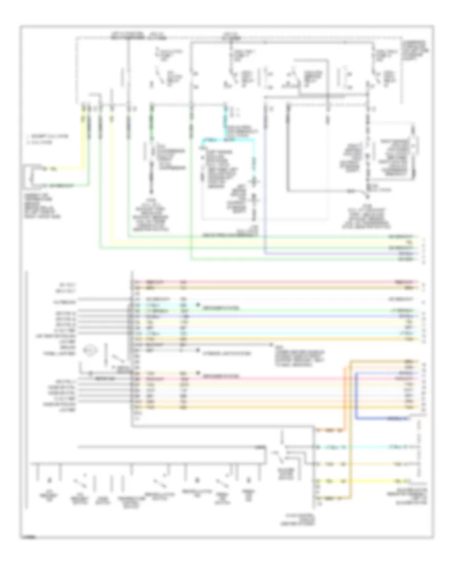
Manual A/C Wiring Diagram (1 of 2) for Chevrolet Malibu LTZ 2008
List of elements for Manual A/C Wiring Diagram (1 of 2) for Chevrolet Malibu LTZ 2008:
- (305 mm from main breakout) (2.4l (vin 5)) j151
- 2.4l (vin b)
- 5 volt ref
- 87a
- A/c clutch fuse 1 10a
- A/c clutch relay
- A/c compressor clutch (front of a/c compressor)
- A/c req sig
- A/c request ind
- A/c request switch
- A10
- A11
- A12
- Air temp dr pos sig
- Ambient air temperature sensor (behind grille, on left side of front impact bar)
- B+ volt
- B10
- B11
- B12
- Blower motor resistor assembly (left of blower motor)
- Blower motor switch
- Cool fan 1 fuse 17 30a
- Cool fan 2 fuse 18 30a
- Cool/ fan 1 relay
- Cool/ fan 2 relay
- Cool/fan ser/par relay
- Defog ind
- Defog switch
- Defogger system
- Dr ctrl a
- Dr ctrl b
- Except 2.4l (vin b)
- Fresh air ind
- Fresh air switch
- G106 (2.4l: at 4 exhaust port, above cmp exhaust sensor) (3.6l: on trans- mission stud, near pnp switch)
- G106 (2.4l: at 4 exhaust port, above cmp exhaust sensor) (3.6l: on transmission stud, near pnp switch)
- G201 (under center console, on right side of front support bracket, next to g203, near bcm)
- Ground
- Hot at all times
- Hot w/ pwr/trn relay energized
- Hvac control module (center of dash)
- Ign 3 volt
- Interior lights system
- J153 (2.4l (vin 5)) (355 mm from main breakout)
- Left engine cooling fan (on front of engine compt)
- Left engine cooling fan diode (2.4l (vin 5)) (between left cooling fan & crankshaft position sensor)
- Logic
- Low ref
- Mode dr ctrl
- Mode dr pos sig
- Mode switch
- Panel lamp rec
- Recirculation ind
- Recirculation switch
- Right engine cooling fan (on front of engine compt)
- Right engine cooling fan diode (2.4l (vin 5)) (between right cooling fan & a/c compressor breakout)
- Tan
- Temperature control switch
- Underhood fuse block (on left side of engine compt)
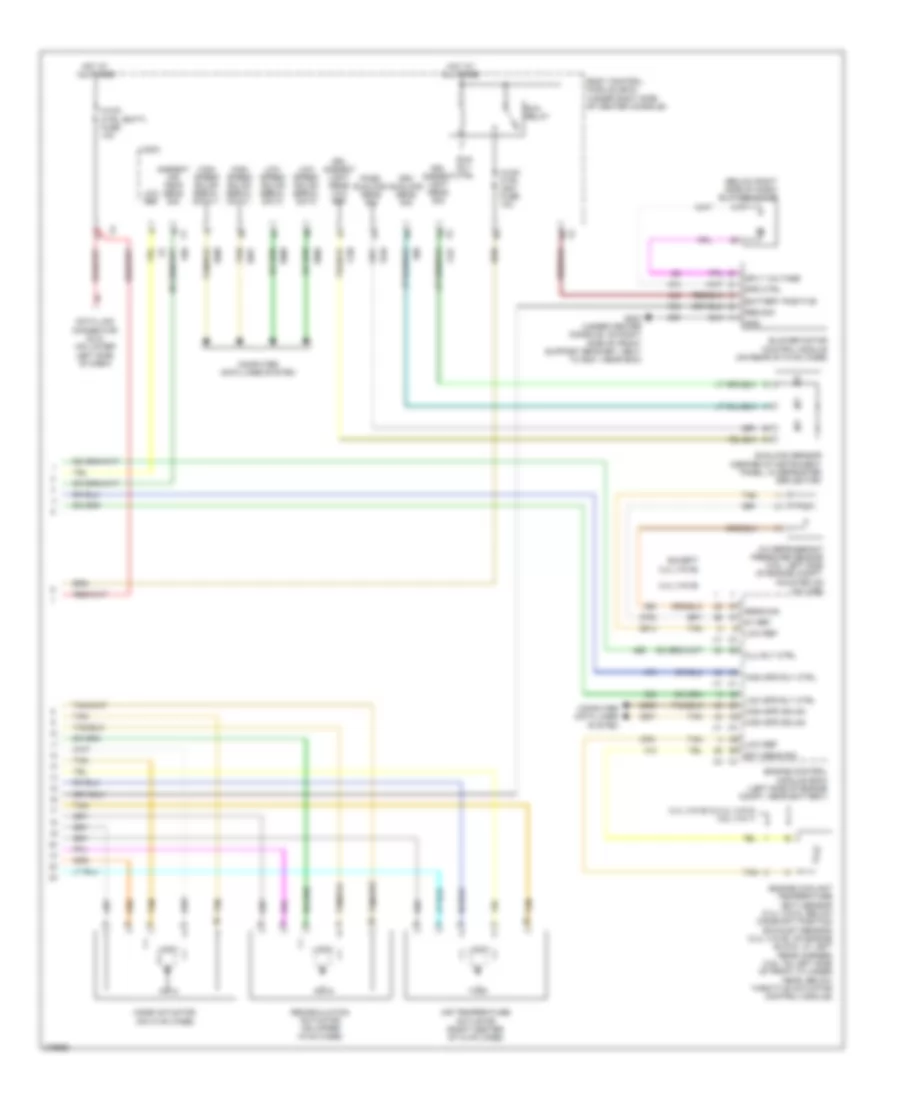
Manual A/C Wiring Diagram (2 of 2) for Chevrolet Malibu LTZ 2008
List of elements for Manual A/C Wiring Diagram (2 of 2) for Chevrolet Malibu LTZ 2008:
- 2.4l (vin b)
- 2.4l (vin b) & 2.4l (vin 5) 3.6l (vin 7)
- 5v ref
- A/c refrigerant pressure sensor (3.6l: left side of engine compt, mounted on a/c line)
- A/c req sig
- After blow
- Air temperature actuator (right center of hvac case)
- Ambient air temp sens sig
- Ambient light sensor (under defrost deflector)
- Blower motor (below right side of dash)
- Body control module (bcm) (under right side of center console)
- Clu rly ctrl
- Computer data lines system
- Data link connector (dlc) (on lower left side of dash)
- Drl ambient light sens low ref
- Drl ambient light sens sig
- Ect sens sig
- Engine control module (ecm) (left side of engine compt, near battery)
- Engine coolant temperature (ect) sensor (2.4l (vin 5): below camshaft position exhaust sensor) (2.4l (vin b): on engine block, at left rear corner) (3.6l: on left side of front cylinder head, below throttle actuator control module)
- Except 2.4l (vin b)
- G203 (under center console, on right side of front support bracket, next to g201, near bcm)
- Ground
- High spd gmlan
- High spd rly ctrl
- High speed gmlan serial data +
- High speed gmlan serial data -
- Hot at all times
- Hvac blower fuse 20a
- Hvac blower high relay
- Hvac ctrl (batt) fuse 10a
- Hvac ctrl (ign) fuse 10a
- Logic
- Low ref
- Low spd rly ctrl
- Low speed gmlan serial data
- Mode actuator (on hvac case)
- Recirculation actuator (on upper hvac case)
- Run relay
- Run rly ctrl
- Sens sig
- Tan