ANTI-LOCK BRAKES
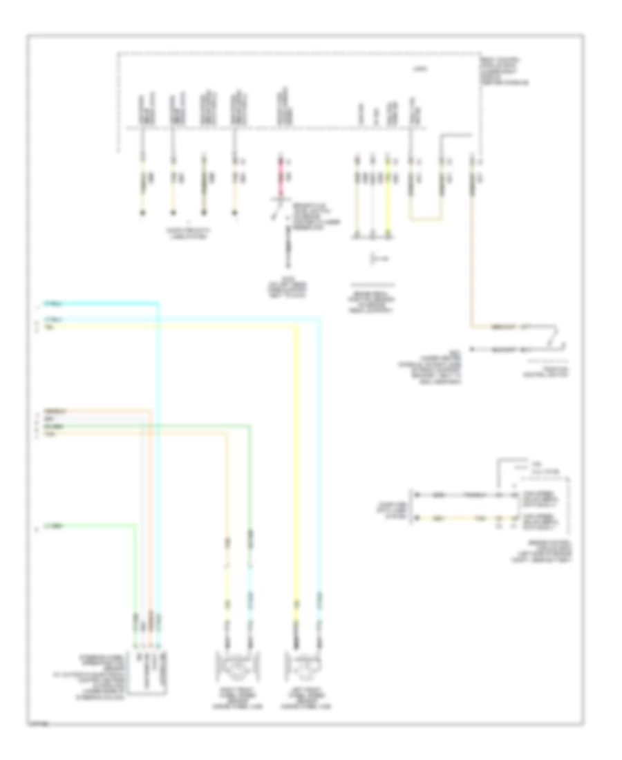
Anti-lock Brakes Wiring Diagram, Except Hybrid (1 of 2) for Chevrolet Malibu LTZ 2008

List of elements for Anti-lock Brakes Wiring Diagram, Except Hybrid (1 of 2) for Chevrolet Malibu LTZ 2008:
- (on left rear core support, next to g104) g109
- 5-volt
- Abs fuse 15 10a
- Abs fuse 24 60a
- Abs ind
- B +
- Batt abs fuse 56 30a
- Brake ind
- Brake pressure modulator valve (bpmv)
- Computer data lines system
- Diagnostic
- Electronic brake control module (ebcm) (mounted to back side of left strut tower)
- G109 (on left rear core support, next to g104)
- Gmlan serial data +
- Gmlan serial data -
- Gnd
- Hot at all times
- Hot in run or start
- Ign
- Ign 1 volt
- Instrument panel cluster (ipc)
- Lateral sig
- Left rear wheel speed sensor (inside wheel hub)
- Lf wheel spd sens low ref
- Lf wheel spd sens sig
- Logic
- Longitudinal sig
- Low ref
- Low speed
- Low speed gmlan serial data
- Low traction ind
- Lr wheel spd sens low ref
- Lr wheel spd sens sig
- Pnk
- Pump motor
- Pump motor control
- Rf wheel spd sens low ref
- Rf wheel spd sens sig
- Right rear wheel speed sensor (inside wheel hub)
- Rr wheel spd sens low ref
- Rr wheel spd sens sig
- Ser data
- Serial data gmlan
- Sig
- Steering wheel pos low ref
- Steering wheel pos sens
- Steering wheel pos sig a
- Steering wheel pos sig b
- Tan
- Traction off ind
- Underhood fuse block (on left side of engine compt)
- W/ automatic electronic controlled ride & handling
- Yaw & lateral accelerometer sensor (w/ automatic electronic controlled ride & handling) (under center console)
- Yaw rate diagnostic
- Yaw rate sens sig
- Yaw rate sens volt ref
- Yaw sens sig
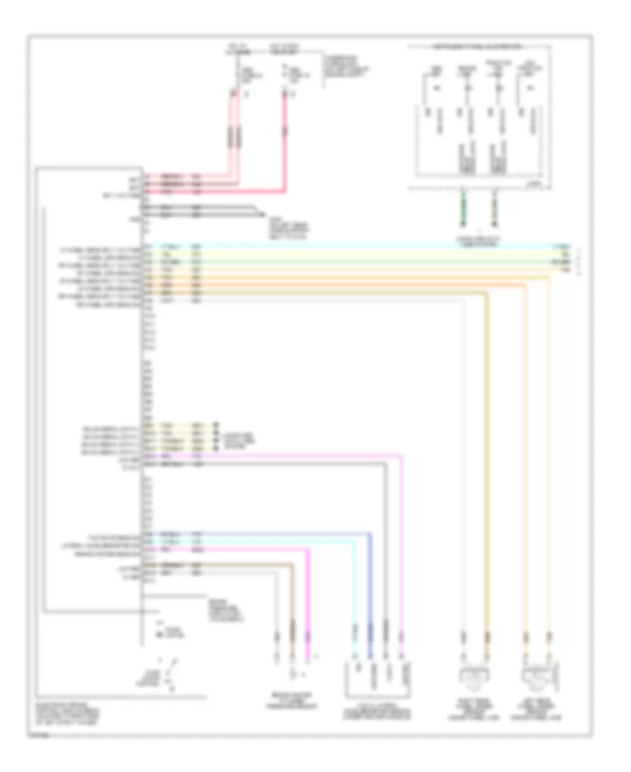
Anti-lock Brakes Wiring Diagram, Except Hybrid (2 of 2) for Chevrolet Malibu LTZ 2008
List of elements for Anti-lock Brakes Wiring Diagram, Except Hybrid (2 of 2) for Chevrolet Malibu LTZ 2008:
- 2.4l (vin b)
- 3.6l
- 5-volt
- 5v ref
- Body control module (bcm) (under right side of center console)
- Brake fluid level sensor
- Brake fluid level switch (on brake master cylinder reservoir)
- Brake pedal position sensor (on brake pedal support)
- Brk pos sens sig
- Computer data lines system
- Data bus (-) gmlan serial high speed
- Engine control module (ecm) (left side of engine compt, near battery)
- G109 (on left rear core support, next to g104)
- G201 (under center console, on right side of front support bracket, next to g203, near bcm)
- Gmlan serial data
- Gmlan serial data bus (+)
- High speed
- High speed gmlan serial data bus (+)
- High speed gmlan serial data bus (-)
- Lateral sig
- Left front wheel speed sensor (inside wheel hub)
- Logic
- Low ref
- Low speed
- Nca
- Pnk
- Right front wheel speed sensor (inside wheel hub)
- Serial data gmlan low speed
- Sig
- Signal
- Steering wheel speed/position sensor (w/ automatic electronic controlled ride & handling) (under base of steering column)
- Tan
- Trac ctrl sw sig
- Traction control switch
- Yaw sens sig
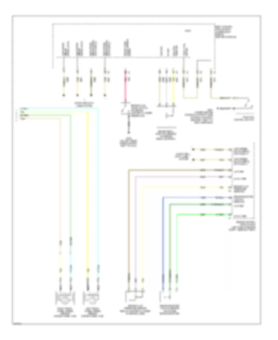
Anti-lock Brakes Wiring Diagram, Hybrid (1 of 2) for Chevrolet Malibu LTZ 2008
List of elements for Anti-lock Brakes Wiring Diagram, Hybrid (1 of 2) for Chevrolet Malibu LTZ 2008:
- 5-volt
- 5v ref
- A10
- A11
- A12
- A13
- A14
- Abs fuse 15 10a
- Abs fuse 24 60a
- Abs ind
- B10
- B11
- B12
- B13
- B14
- Bat
- Brake ind
- Brake master cylinder pressure sensor
- Brake master sens sig
- Brake pressure modulator valve (bpmv)
- C10
- C11
- C12
- C13
- C14
- Computer data lines system
- Electronic brake control module (ebcm) (mounted to back side of left strut tower)
- G109 (on left rear core support, next to g104)
- Gmlan serial data (+)
- Gmlan serial data (-)
- Gnd
- Hot at all times
- Hot in run or start
- Ign
- Ign 1 voltage
- Instrument panel cluster (ipc)
- Lateral accelerometer sig
- Left rear wheel speed sensor (inside wheel hub)
- Lf wheel sens sply voltage
- Lf wheel spd sens sig
- Logic
- Low ref
- Low speed
- Low speed gmlan serial data
- Low traction ind
- Lr wheel sens sply voltage
- Lr wheel spd sens sig
- Pnk
- Pump motor
- Pump motor control
- Rf wheel sens sply voltage
- Rf wheel spd sens sig
- Right rear wheel speed sensor (inside wheel hub)
- Rr wheel sens sply voltage
- Rr wheel spd sens sig
- Ser data
- Serial data gmlan
- Sig
- Tan
- Traction off ind
- Underhood fuse block (on left side of engine compt)
- Yaw & lateral accelerometer sensor (under center console)
- Yaw rate sens sig
- Yaw sens
Anti-lock Brakes Wiring Diagram, Hybrid (2 of 2) for Chevrolet Malibu LTZ 2008
List of elements for Anti-lock Brakes Wiring Diagram, Hybrid (2 of 2) for Chevrolet Malibu LTZ 2008:
- 5-volt ref
- 5v ref
- Body control module (bcm) (under right side of center console)
- Brake booster vacuum sens sig
- Brake booster vacuum sensor (on power brake booster)
- Brake fluid level sensor
- Brake fluid level switch (on brake master cylinder reservoir)
- Brake fluid pressure sens sig
- Brake fluid pressure sensor (below master cylinder, on brake lines)
- Brake pedal position sensor (on brake pedal support)
- Brk pos sens sig
- Computer data lines system
- Data bus (-)
- Engine control module (ecm) (left side of engine compt, near battery)
- G109 (on left rear core support, next to g104)
- G201 (under center console, on right side of front support bracket, next to g203, near bcm)
- Gmlan serial data
- Gmlan serial data bus (+)
- Gmlan serial high speed
- High speed
- High speed gmlan serial data bus (+)
- High speed gmlan serial data bus (-)
- Left front wheel speed sensor (inside wheel hub)
- Logic
- Low ref
- Low speed
- Nca
- Pnk
- Right front wheel speed sensor (inside wheel hub)
- Serial data gmlan low speed
- Signal
- Tan
- Trac ctrl sw sig
- Traction control switch