ENGINE PERFORMANCE
2.4L VIN 5
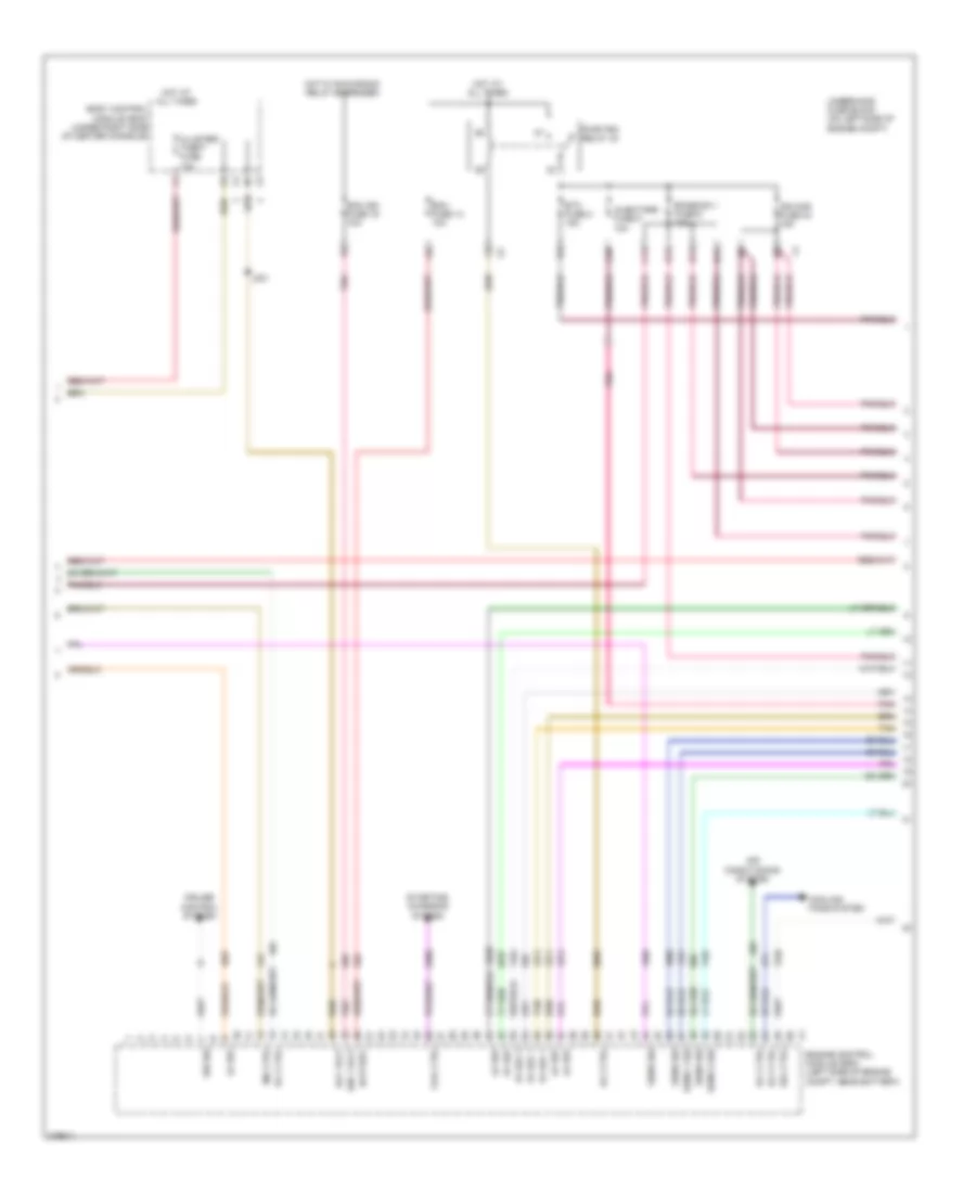
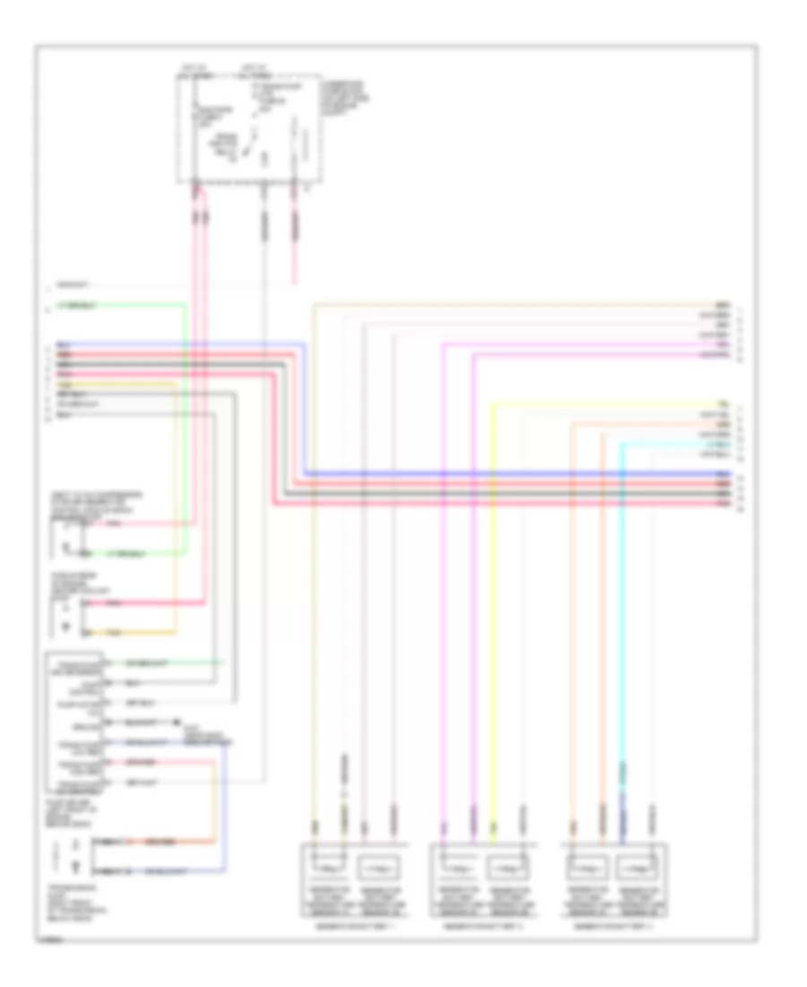
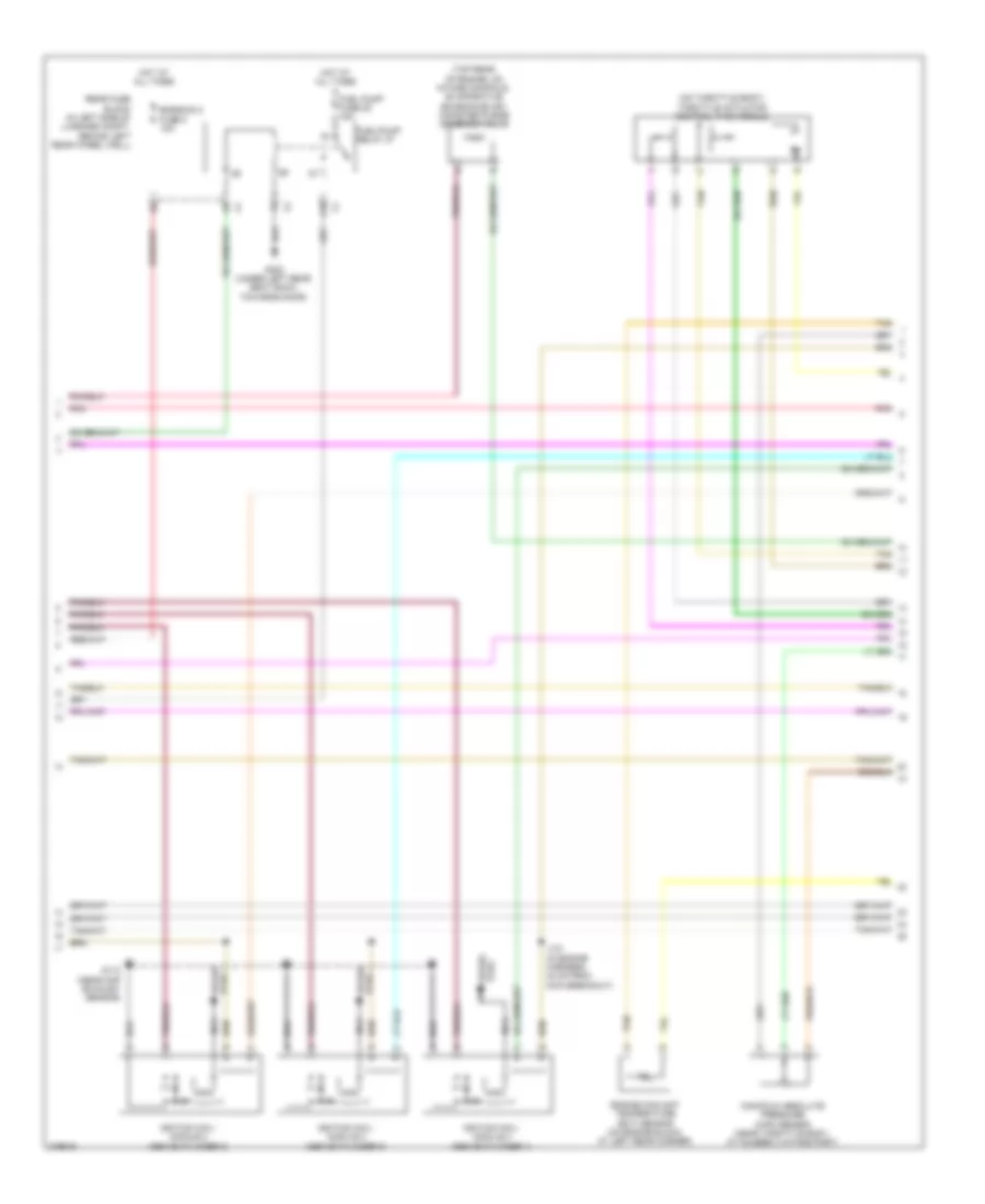
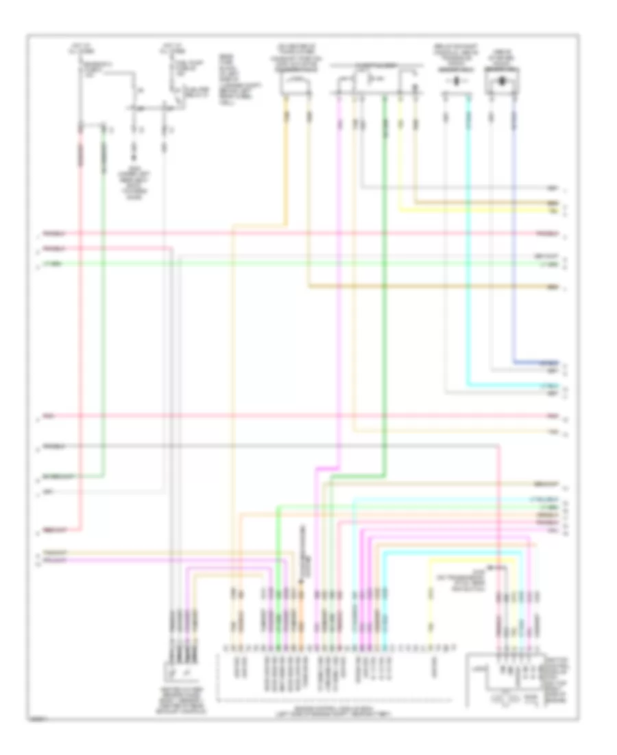
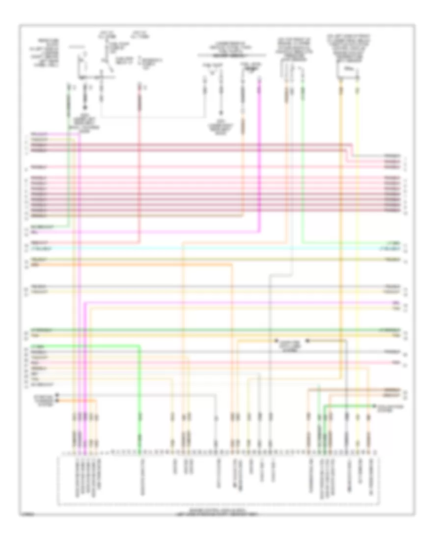
2.4L VIN 5, Engine Controls Wiring Diagram (1 of 4) for Chevrolet Malibu LTZ 2008

List of elements for 2.4L VIN 5, Engine Controls Wiring Diagram (1 of 4) for Chevrolet Malibu LTZ 2008:
- (under right rear seat back) g301
- 5v ref
- 5v ref 1
- 5v ref 2
- A/c refrigerant pressure sensor
- A10
- Acc
- Anti-lock brakes system
- Computer data lines system
- Cooling fans system
- Emission 2 fuse 5 10a
- Engine control module (ecm) (left side of engine compt, near battery)
- Engine coolant temperature (ect) sensor (below camshaft position exhaust sensor)
- Engine oil pressure (eop) switch (front center of engine, above starter)
- Evaporative emission (evap) canister purge solenoid valve (top rear of engine, on intake manifold)
- Fuel level sensor
- Fuel pump
- Fuel pump & sender assembly (under rear of vehicle, in fuel tank)
- Fuel pump fuse 25 15a
- Fuel/ pmp relay 37
- G302 (under left rear seat back, towards door)
- Gmlan data
- Hot at all times
- Ign
- Ignition switch
- Instrument panel cluster (ipc)
- Logic
- Low ref
- Malfunc- tion indicator lamp
- Manifold absolute pressure (map) sensor (front of engine, on intake manifold, near cylinder 3)
- Off
- Park/ neutral sig
- Pnk
- Press sw sig a
- Rear fuse block (in left side of luggage compt, behind left rear wheel well)
- Rly ctrl
- Run
- Sens sig
- Serial bus+
- Serial bus-
- Sol ctrl
- Start
- Starting/ charging system
- Sw sig
- Tan
- Transmissions system
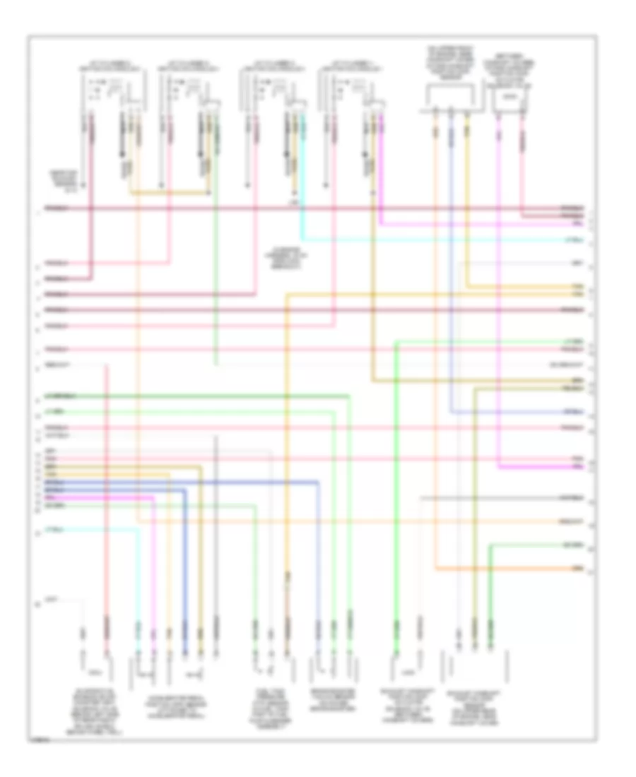
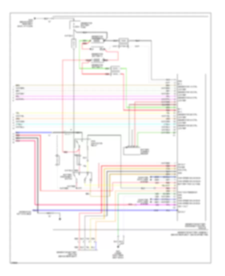
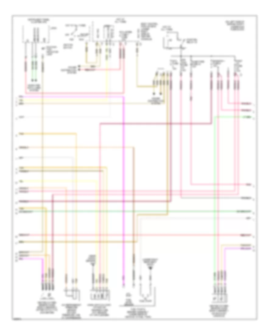
2.4L VIN 5, Engine Controls Wiring Diagram (2 of 4) for Chevrolet Malibu LTZ 2008
List of elements for 2.4L VIN 5, Engine Controls Wiring Diagram (2 of 4) for Chevrolet Malibu LTZ 2008:
- 5v ref
- 5v ref 1
- 5v ref 2
- A10
- Acc volt
- Air conditioning system
- B11
- Battery
- Body control module (bcm) (under right side of center console)
- C11
- Cluster/ theft fuse 10a
- Coil ctrl
- Cooling fans system
- Cruise control system
- D11
- E11
- Ecm fuse 13 10a
- Ecm ign fuse 16 10a
- Emission 1 fuse 6 10a
- Engine control module (ecm) (left side of engine compt, near battery)
- Etc fuse 2 15a
- Hot at all times
- Hot w/ run/crank relay energized
- Ign 1 volt
- Ign mod fuse 43 15a
- Injectors fuse 5 10a
- J201
- Lo ref
- Mil ctrl
- Pnk
- Pwr/trn relay 33
- Rly ctrl
- Sens 1 sig
- Sens 2 sig
- Sens sig
- Sol ctrl
- Starting/ charging system
- Sw sig
- Tan
- Underhood fuse block (on left side of engine compt)
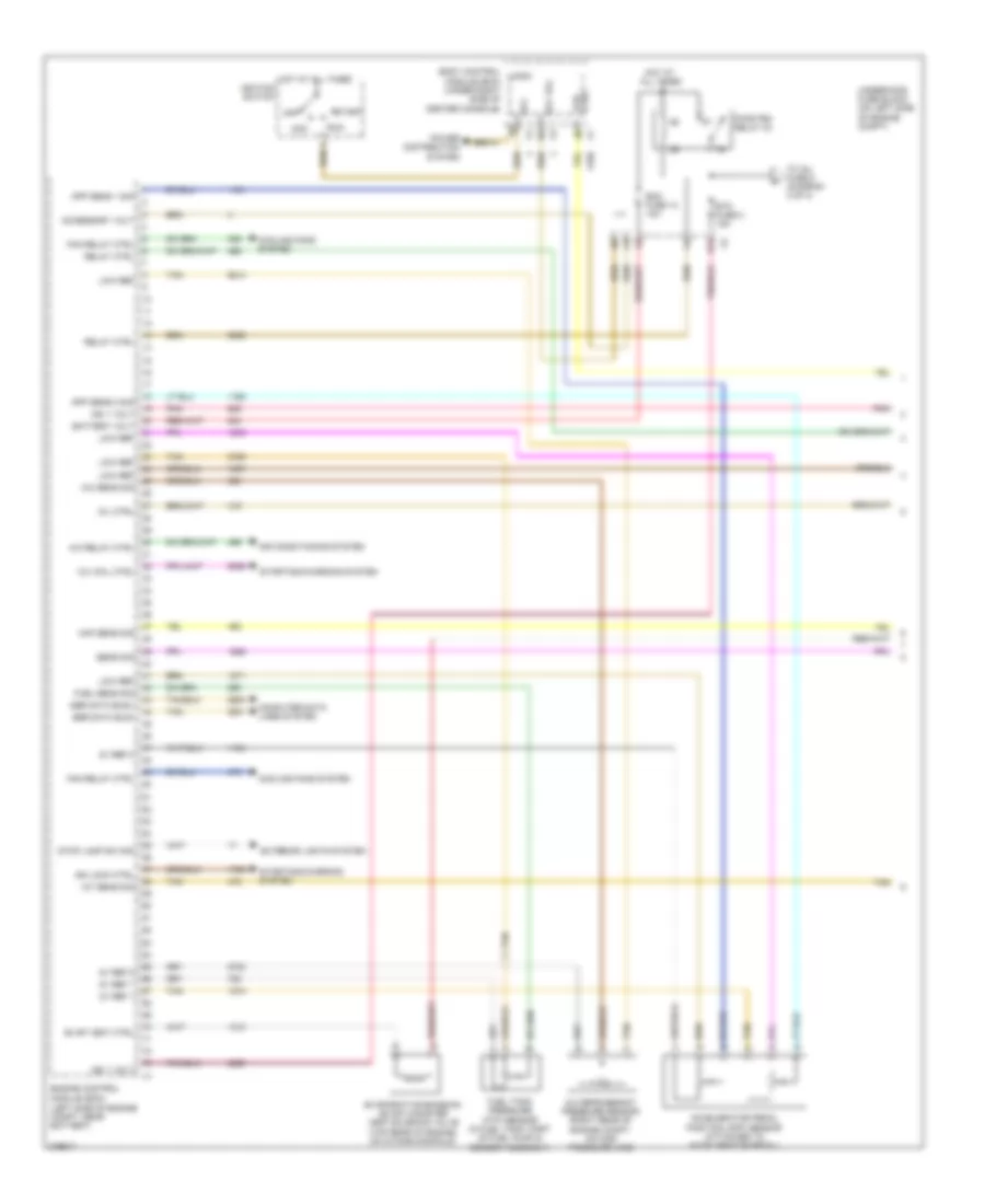
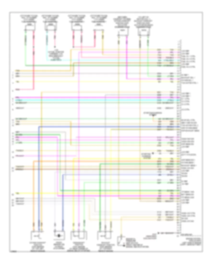
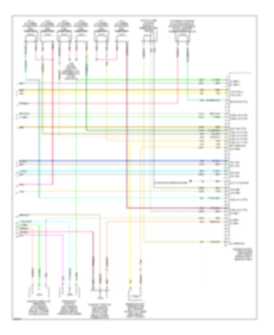
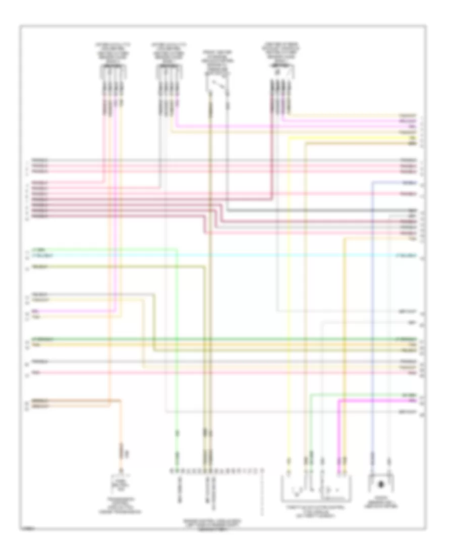
2.4L VIN 5, Engine Controls Wiring Diagram (3 of 4) for Chevrolet Malibu LTZ 2008
List of elements for 2.4L VIN 5, Engine Controls Wiring Diagram (3 of 4) for Chevrolet Malibu LTZ 2008:
- (at cylinder 1) ignition coil/module 1
- (at cylinder 2) ignition coil/module 2
- (at cylinder 3) ignition coil/module 3
- (at cylinder 4) ignition coil/module 4
- (between camshaft covers) intake camshaft position (cmp) actuator solenoid valve
- (in engine harness, 40 mm from main breakout)
- (near cmp exhaust sensor) g110
- (on upper front of engine, near camshaft cover) intake camshaft position (cmp) sensor
- Accelerator pedal position (app) sensor (attached to accelerator pedal)
- Brake booster vacuum sensor (on power brake booster)
- Evaporative emission (evap) canister vent solenoid valve (behind left side of rear fascia splash shield, behind wheel well)
- Exhaust camshaft position (cmp) actuator solenoid valve (between camshaft covers)
- Exhaust camshaft position (cmp) sensor (on upper rear of engine, near camshaft cover)
- Fuel tank pressure (ftp) sensor (in fuel tank, part of fuel pump & sender assembly)
- J121
- Nca
- Plug spark
- Pnk
- Spark plug
- Tan
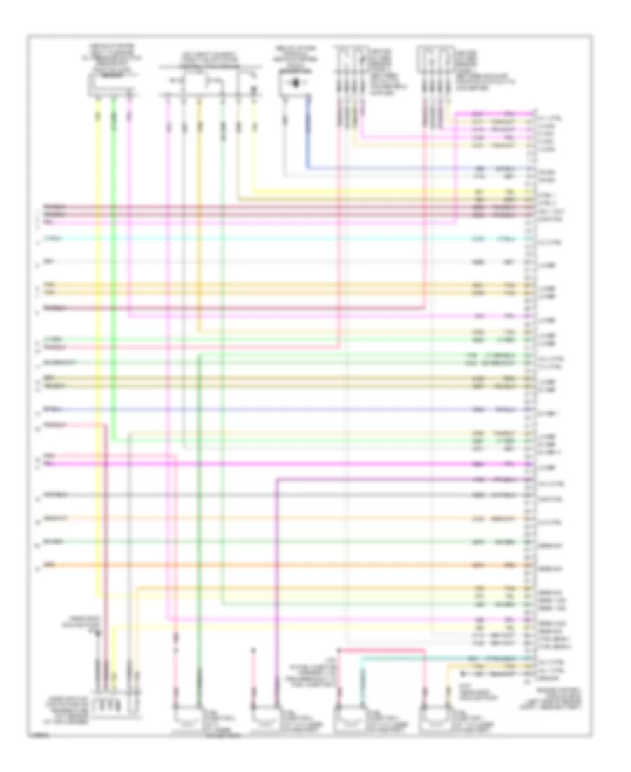
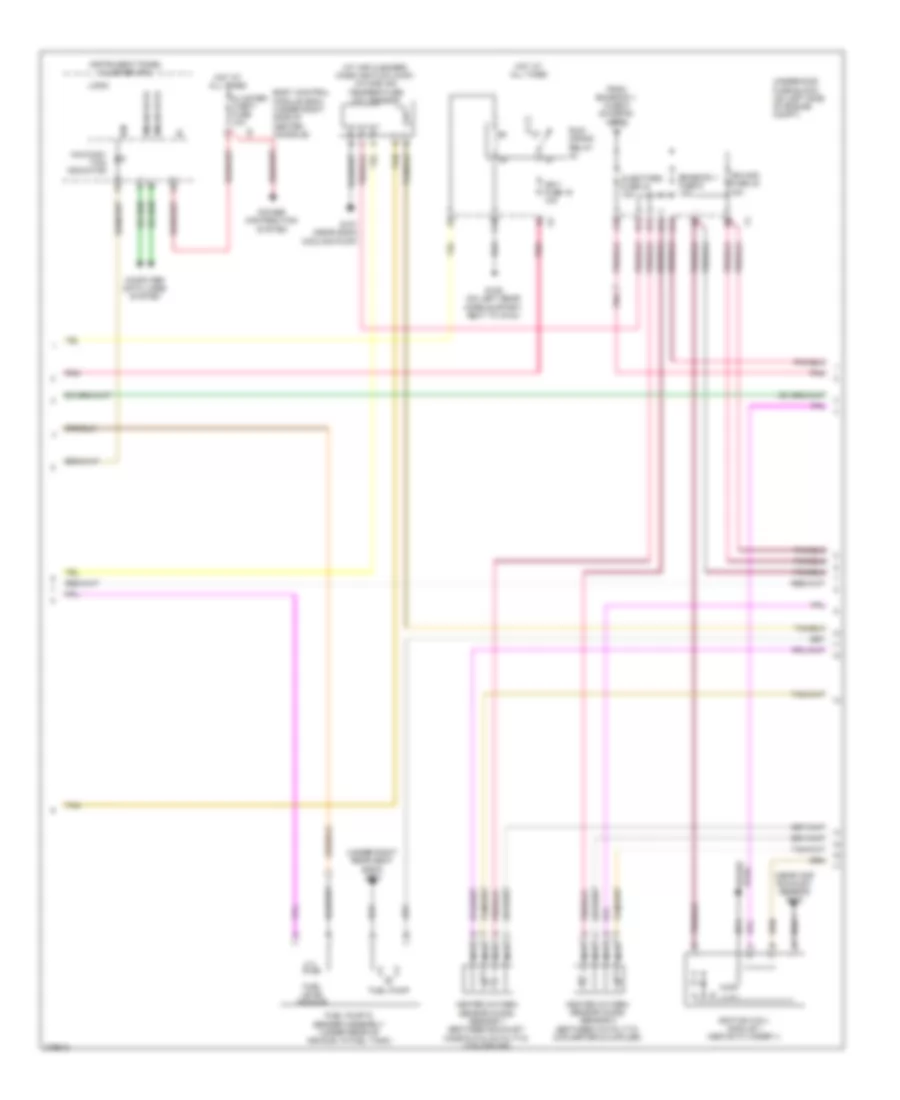
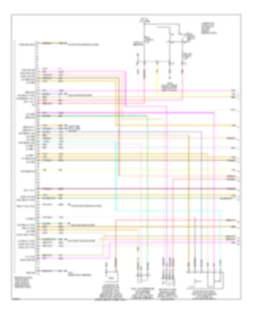
2.4L VIN 5, Engine Controls Wiring Diagram (4 of 4) for Chevrolet Malibu LTZ 2008
List of elements for 2.4L VIN 5, Engine Controls Wiring Diagram (4 of 4) for Chevrolet Malibu LTZ 2008:
- (above starter, next to engine oil pressure switch) crankshaft position (ckp) sensor
- (below intake manifold, above starter) knock sensor (ks)
- (in fuel injector harness, 4 cm from breakout to fuel injector 2)
- (near sgcm cooling pump) g107
- (on throttle body) throttle actuator control (tac) module
- 5v ref
- 5v ref 1
- 5v ref 2
- Cmp ctrl
- Ctrl 1
- Ctrl 2
- Ctrl sens 1
- Ctrl sens 2
- Engine control module (ecm) (left side of engine compt, near battery)
- Fuel injector 1 (at 1 cylinder intake port)
- Fuel injector 2 (at 2 cylinder intake port)
- Fuel injector 3 (at 3 cylinder intake port)
- Fuel injector 4 (at 4 cylinder intake port)
- G107 (near sgcm cooling pump)
- Gnd
- Ground
- Heated oxygen sensor (ho2s) 1 (between exhaust manifold & catalytic converter)
- Heated oxygen sensor (ho2s) 2 (between catalytic converter & muffler)
- Hi sig
- Ic 1 ctrl
- Ic 2 ctrl
- Ic 3 ctrl
- Ic 4 ctrl
- Ign
- Ign 1 volt
- Inj 1 ctrl
- Inj 2 ctrl
- Inj 3 ctrl
- Inj 4 ctrl
- J130
- Ks sig
- Lo ref
- Lo sig
- Mass air flow (maf)/intake air temperature (iat) sensor (at air cleaner)
- Nca
- Pnk
- Sens 1 sig
- Sens 2 sig
- Sens sig
- Sig
- Tan
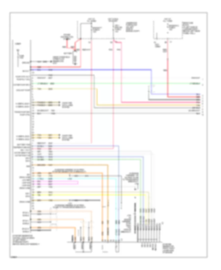
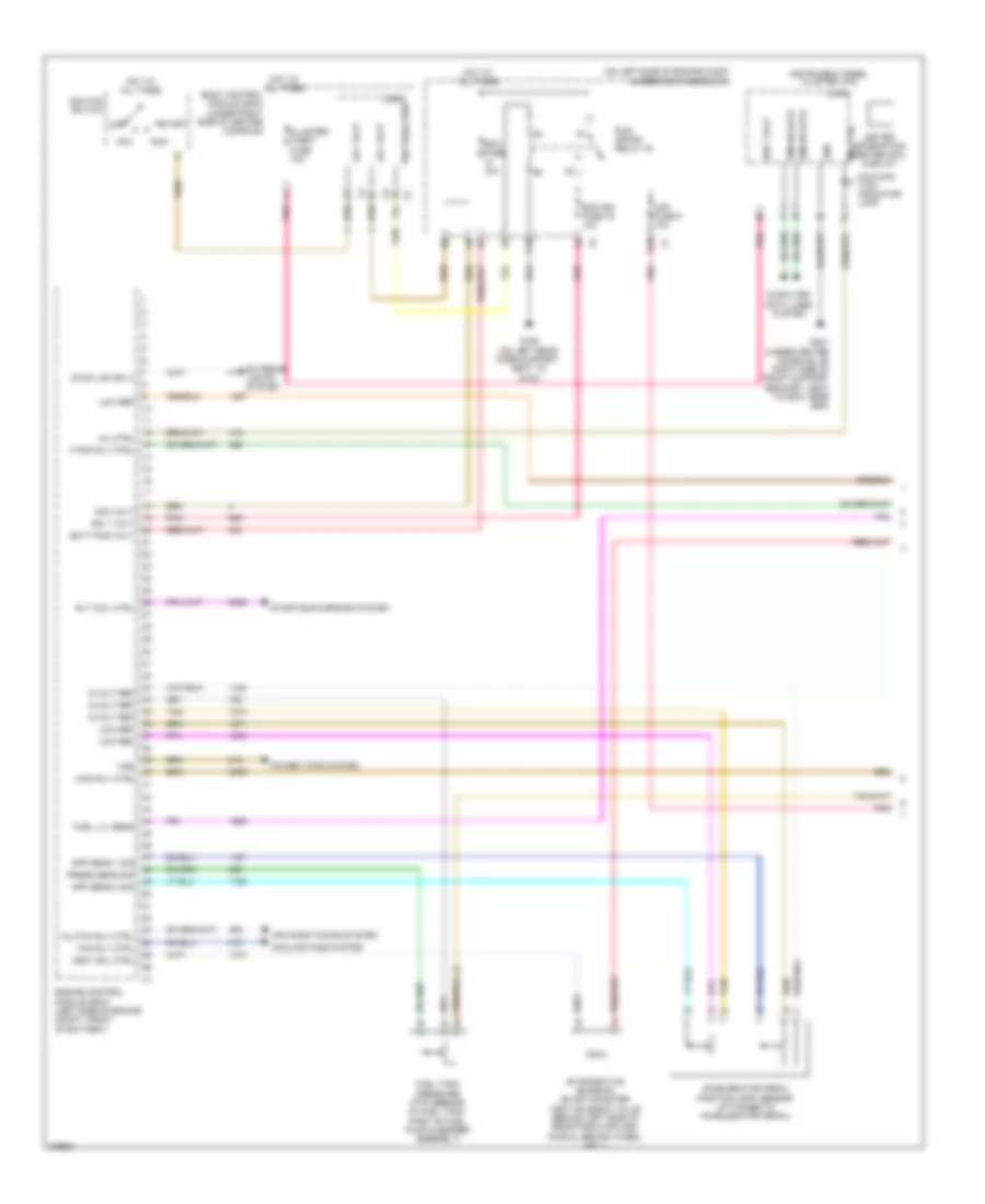
2.4L VIN 5, Hybrid System Wiring Diagram (1 of 3) for Chevrolet Malibu LTZ 2008
List of elements for 2.4L VIN 5, Hybrid System Wiring Diagram (1 of 3) for Chevrolet Malibu LTZ 2008:
- (in engine harness, 100 mm from inline to transmission breakout) j103
- (in engine harness, 80 mm from starter generator x2 breakout)
- (near windshield wiper fluid reservoir) g101
- (not used)
- 12v
- 36-volt
- 36v
- A nca
- Bas batt fuse 51 10a
- Battery
- Battery pos
- Computer data lines system
- Coolant pump
- Drain wire
- Emission 2 fuse 5 10a
- Fuse 175a
- Gnd
- Ground
- Hi serial bus +
- Hi serial bus -
- Hot at all times
- Hot in run or start
- Ign 1 bas ign fuse 3 10a
- Ign 1 volt
- J nca
- J101 (in engine harness, 50 mm from inline to transmission breakout)
- J102
- J105 (in engine harness, 30 mm from tac module breakout)
- K nca
- Logic
- Loop sig
- Low ref
- Motor +
- Motor -
- Motor positive
- Nca
- Pnk
- Power distribution system
- Pump ctrl
- Pump mtr volt
- Pump rly coil
- Rear fuse block (in left side of luggage compt, behind left rear wheel well)
- Red
- Shield
- Sig 1
- Sig 2
- Sig 3
- Sig 4
- Starter generator (front right lower side of engine)
- Starter generator control module (sgcm) (in left front of engine compt, behind headlamp assembly)
- Stud u
- Stud v
- Stud w
- Tan
- Temperature sig
- Trans pump drv
- Underhood fuse block (on left side of engine compt)
- Water pump sply
2.4L VIN 5, Hybrid System Wiring Diagram (2 of 3) for Chevrolet Malibu LTZ 2008
List of elements for 2.4L VIN 5, Hybrid System Wiring Diagram (2 of 3) for Chevrolet Malibu LTZ 2008:
- (middle rear of engine) heater coolant pump
- (next to a/c compressor) starter generator control module (sgcm) coolant pump
- A trans pump driver error
- A12
- B pump control
- B10
- Bas pmps fuse 5 20a
- C pump motor vol
- C12
- F trans pump low ref
- G trans pump high ref
- G107 (near sgcm cooling pump)
- Generator battery 1
- Generator battery 2
- Generator battery 3
- Generator battery temperature sensor 1a
- Generator battery temperature sensor 1b
- Generator battery temperature sensor 2a
- Generator battery temperature sensor 2b
- Generator battery temperature sensor 3a
- Generator battery temperature sensor 3b
- Ground
- H trans pump sw control
- Hot at all times
- Nca
- Pnk
- Pump driver (left front of engine, behind sgcm)
- Red
- Tan
- Trans pmp mtr relay
- Trans pump mtr fuse 52 20a
- Transmission pump (right front of transmission, below sgcm)
- Underhood fuse block (on left side of engine compt)
2.4L VIN 5, Hybrid System Wiring Diagram (3 of 3) for Chevrolet Malibu LTZ 2008
List of elements for 2.4L VIN 5, Hybrid System Wiring Diagram (3 of 3) for Chevrolet Malibu LTZ 2008:
- 200a
- 36-volt
- B+ 1
- B+ 2
- B+ 3
- Battery current sensor
- Battery disconnect switch
- Battery pos voltage
- Computer data lines system
- Fan ctrl
- Fan tach feedback
- G301 (under right rear seat back)
- G402 (behind right rear seat back, at floor)
- Generator 1a ctrl
- Generator 1b ctrl
- Generator 2a ctrl
- Generator 2b ctrl
- Generator 3a ctrl
- Generator 3b ctrl
- Generator battery 1
- Generator battery 2
- Generator battery 3
- Generator battery assembly (behind rear seat, above spare tire)
- Generator battery disconnect control module
- Generator battery fuse
- Generator battery vent fan (behind rear seat)
- Gnd
- High speed gmlan bus+
- High speed gmlan bus-
- Ign 1 volt
- Information not available
- J410
- Low ref
- Main contactor relay
- Nca
- Pnk
- Power
- Red
- Tan
2.4L VIN B
2.4L VIN B, Engine Performance Wiring Diagram (1 of 4) for Chevrolet Malibu LTZ 2008
List of elements for 2.4L VIN B, Engine Performance Wiring Diagram (1 of 4) for Chevrolet Malibu LTZ 2008:
- (left side of engine compt, near battery)
- 12v coil ctrl
- 5v ref 1
- 5v ref 2
- A/c refrigerant pressure sensor (right rear of engine compt, on high pressure line)
- A/c relay ctrl
- A/c sens sig
- Acc
- Acc vol
- Accelerator pedal position (app) sensor (attached to accelerator pedal)
- Accessory volt
- Air conditioning system
- App sens 1 sig
- App sens 2 sig
- Battery volt
- Body control logic module (bcm) (under right side of center console)
- Computer data lines system
- Cooling fans system
- Ctrl coil
- D12
- Ecm fuse 13 10a
- Engine control module (ecm)
- Etc fuse 2 15a
- Evap vent ctrl
- Evaporative emission (evap) canister vent solenoid valve (top rear of engine, on intake manifold)
- Exterior lights system
- Fan relay ctrl
- Fuel sens sig
- Fuel tank pressure (ftp) sensor (in fuel tank, part of fuel pump & sender assembly)
- Hot at all times
- Iat sens sig
- Ign 1 volt
- Ign lock ctrl
- Ignition switch
- Low ref
- Maf sens sig
- Mil ctrl
- Off
- Pnk
- Power distribution system
- Pwr/trn relay 33
- Relay ctrl
- Run
- Sens sig
- Ser data bus+
- Ser data bus-
- Start
- Starting/charging system
- Stop lamp sw sig
- Tan
- Tan c
- To inj fuse 5 (diagram 2 of 4)
- Underhood fuse block (on left side of engine compt)
2.4L VIN B, Engine Performance Wiring Diagram (2 of 4) for Chevrolet Malibu LTZ 2008
List of elements for 2.4L VIN B, Engine Performance Wiring Diagram (2 of 4) for Chevrolet Malibu LTZ 2008:
- (at air cleaner) mass air flow (maf)/ intake air temperature (iat) sensor
- (near cmp exhaust sensor) g110
- (under right rear seat back) g301
- A10
- B11
- Body control module (bcm) (under right side of center console)
- C10
- C11
- Cluster/ theft fuse 10a
- Computer data lines system
- D11
- E11
- Emission 1 fuse 6 10a
- From emission 1 fuse 6 (diagram 1 of 4)
- Fuel level sensor
- Fuel pump
- Fuel pump & sender assembly (under rear of vehicle, in fuel tank)
- G107 (near sgcm cooling pump)
- G109 (on left rear core support, next to g104)
- Gmlan data
- Heated oxygen sensor (ho2s) sensor 1 (between exhaust manifold & catalytic converter)
- Heated oxygen sensor (ho2s) sensor 2 (between catalytic converter & muffler)
- Hot at all times
- Ign
- Ign 1 fuse 16 10a
- Ign mod fuse 43 15a
- Ignition coil/ module 1 (above cylinder 1)
- Injectors fuse 44 10a
- Instrument panel cluster (ipc)
- Logic
- Malfunc- tion indicator
- Nca
- Plug spark
- Pnk
- Power distribution system
- Run/ crank relay
- Tan
- Underhood fuse block (on left side of engine compt)
2.4L VIN B, Engine Performance Wiring Diagram (3 of 4) for Chevrolet Malibu LTZ 2008
List of elements for 2.4L VIN B, Engine Performance Wiring Diagram (3 of 4) for Chevrolet Malibu LTZ 2008:
- (on throttle body) throttle actuator control (tac) module
- (top rear of engine, on intake manifold) evaporative emission (evap) canister purge solenoid valve
- A10
- Emission 2 fuse 5 10a
- Engine coolant temperature (ect) sensor (on engine block, at left rear corner)
- Fuel pump fuse 25 15a
- Fuel/pump relay 37
- G110 (near cmp exhaust sensor)
- G302 (under left rear seat back, towards door)
- Hot at all times
- Ignition coil/ module 2 (above cylinder 2)
- Ignition coil/ module 3 (above cylinder 3)
- Ignition coil/ module 4 (above cylinder 4)
- J121 (in engine harness, 40 mm from main breakout)
- Manifold absolute pressure (map) sensor (near throttle body, at number 3 intake port)
- Nca
- Plug spark
- Pnk
- Rear fuse block (in left side of luggage compt, behind left rear wheel well)
- Tan
2.4L VIN B, Engine Performance Wiring Diagram (4 of 4) for Chevrolet Malibu LTZ 2008
List of elements for 2.4L VIN B, Engine Performance Wiring Diagram (4 of 4) for Chevrolet Malibu LTZ 2008:
- (attached to fuel rail, at number 1 cylinder) fuel injector 1
- (attached to fuel rail, at number 2 cylinder) fuel injector 2
- (attached to fuel rail, at number 3 cylinder) fuel injector 3
- (attached to fuel rail, at number 4 cylinder) fuel injector 4
- (between camshaft covers) intake camshaft position (cmp) actuator solenoid valve
- (to left of ignition coil 1) exhaust camshaft position (cmp) actuator solenoid solenoid valve
- 12v ref
- 5v ref
- 5v ref 1
- Ckp sens sig 1
- Cmp exhaust sens
- Cmp intake sens
- Crankshaft position (ckp) sensor (at rear corner of engine, below starter)
- Duty cycle sig
- Ect sens sig
- Engine control module (ecm) (left side of engine compt, near battery)
- Engine oil pressure (eop) switch (front center of engine, above starter)
- Evap sol ctrl
- Exhaust camshaft position (cmp) sensor (at top right rear of engine)
- Exhaust sens 1
- Exhaust sol 1
- Fuel inj 1 ctrl
- Fuel inj 2 ctrl
- Fuel inj 3 ctrl
- Fuel inj 4 ctrl
- G107 (near sgcm cooling pump)
- Gen turn on sig
- Ho2s high sig
- Ho2s low ctrl
- Ho2s low sig
- Ic 1 ctrl
- Ic 2 ctrl
- Ic 3 ctrl
- Ic 4 ctrl
- Intake camshaft position (cmp) sensor (at top left rear of engine)
- Intake sens 1
- Intake sol 1
- J130 (in fuel injector harness, 4 cm from breakout to fuel injector 2)
- Knock sensor (ks) (in front of starter)
- Ks sig
- Low ref
- Low ref 1
- Map sens sig
- Pnk
- Sig ground
- Starting/ charging system
- Starting/charging system
- Sw sig
- Tac motor ctrl 1
- Tac motor ctrl 2
- Tan
- Tp sens 1 sig
- Tp sens 2 sig
3.5L VIN N
3.5L VIN N, Engine Performance Wiring Diagram (1 of 4) for Chevrolet Malibu LTZ 2008
List of elements for 3.5L VIN N, Engine Performance Wiring Diagram (1 of 4) for Chevrolet Malibu LTZ 2008:
- (left side of engine compt, near battery)
- 5v ref 1
- 5v ref 2
- A/c relay ctrl
- A/c sens sig
- Accelerator pedal position (app) sensor (attached to accelerator pedal)
- Accessory volt
- Air conditioning system
- App sens 1 sig
- App sens 2 sig
- C10
- Computer data lines system
- Cooling fans system
- Ecm fuse 51 10a
- Ecm ign fuse 3 10a
- Engine control module (ecm)
- Evap vent ctrl
- Evaporative emission (evap) canister vent solenoid valve (behind left side of rear fascia splash shield, behind wheel well)
- Fan relay ctrl
- Fuel relay ctrl
- Fuel tank pressure (ftp) sensor (in fuel tank, part of fuel pump & sender assembly)
- G107 (near knock sensor)
- G109 (on left rear core support, next to g104)
- Ground
- Heated oxygen sensor (ho2s) bank 1 sensor 2 (after catalytic) converter)
- Ho2s high sig
- Ho2s low ctrl
- Ho2s low sig
- Hot at all times
- Iat sens sig
- Ign 1 volt
- Lamp sw sig
- Low ref
- Maf sens sig
- Mil ctrl
- Nca
- Park/neutral
- Pnk
- Relay coil ctrl
- Relay ctrl
- Run/ crank relay
- Sens sig
- Ser data +
- Ser data -
- Starting/charging system
- Stop lp relay 49
- Tan
- Underhood fuse block (on left side of engine compt)
3.5L VIN N, Engine Performance Wiring Diagram (2 of 4) for Chevrolet Malibu LTZ 2008
List of elements for 3.5L VIN N, Engine Performance Wiring Diagram (2 of 4) for Chevrolet Malibu LTZ 2008:
- (near knock sensor) g107
- (on left side of engine compt) underhood fuse block
- (under right rear seat back) g301
- A/c refrigerant pressure sensor (on high pressure line, at compressor)
- A10
- Acc
- Acc vol
- B11
- Body control module (bcm) (under right side of center console)
- C11
- Cluster/ theft fuse 10a
- Coil ctrl
- Computer data lines system
- D11
- Emission 1 fuse 6 10a
- Etc fuse 15a
- Fuel level sensor
- Fuel pump
- Fuel pump & sender assembly (under rear of vehicle, in fuel tank)
- Gmlan data
- Gnd
- Heated oxygen sensor (ho2s) bank 2 sensor 1 (on exhaust manifold)
- Heated oxygen sensor (ho2s) bank 2 sensor 2 (after catalytic) converter)
- Hot at all times
- Ign
- Ign mod fuse 15a
- Ignition switch
- Injectors fuse 44 10a
- Instrument panel cluster (ipc)
- Logic
- Malfunc- tion indicator lamp
- Mass air flow (maf)/ intake air temperature (iat) sensor (at air cleaner)
- Nca
- Off
- Pnk
- Post o2 fuse 10a
- Power distribution system
- Pwr/trn relay 33
- Run
- Sig
- Start
- Stop lp
- Tan
3.5L VIN N, Engine Performance Wiring Diagram (3 of 4) for Chevrolet Malibu LTZ 2008
List of elements for 3.5L VIN N, Engine Performance Wiring Diagram (3 of 4) for Chevrolet Malibu LTZ 2008:
- (above starter) knock sensor (ks) 1
- (below exhaust manifold, above transaxle) knock sensor (ks) 2
- (on center of timing cover)
- A10
- Camshaft position (cmp) actuator solenoid valve
- Cpm sens sig
- Emission 2 fuse 5 10a
- Engine control module (ecm) (left side of engine compt, near battery)
- Fuel pump fuse 25 15a
- Fuel/pmp relay 37
- G106 (on transmission, stud, near pnp switch)
- G302 (under left rear seat back, towards door)
- Gnd
- Heated oxygen sensor (ho2s) bank 1 sensor 1 (center of rear exhaust manifold)
- Ho2s high sig
- Ho2s low sig
- Hot at all times
- Ic 1 ctrl
- Ic 1/4
- Ic 2 ctrl
- Ic 2/5
- Ic 3 ctrl
- Ic 3/6
- Ign
- Ignition control module (icm) (on top right side of engine)
- Logic
- Low ref
- Map sens sig
- Nca
- Nca nca
- Pnk
- Rear fuse block (in left side of luggage compt, behind left rear wheel well)
- Speed sig
- Starting/charging system
- Tan
- Throttle body
- Tp sens 1 sig
- Tp sens 2 sig
- Turn on sig
3.5L VIN N, Engine Performance Wiring Diagram (4 of 4) for Chevrolet Malibu LTZ 2008
List of elements for 3.5L VIN N, Engine Performance Wiring Diagram (4 of 4) for Chevrolet Malibu LTZ 2008:
- (at 1 cylinders intake port) fuel injector 1
- (at 2 cylinders intake port) fuel injector 2
- (at 3 cylinders intake port) fuel injector 3
- (at 4 cylinders intake port) fuel injector 4
- (at 5 cylinders intake port) fuel injector 5
- (at 6 cylinders intake port) fuel injector 6
- (on oil filter housing) engine oil pressure (eop) sensor
- (top rear of engine, on intake manifold) evaporative emission (evap) canister purge solenoid valve
- 5v ref 1
- 5v ref 2
- A pnk
- Camshaft position (cmp) sensor (above timing chain cover, below power steering pump)
- Crankshaft position (ckp) sensor (right side of engine, behind harmonic balancer)
- Duty cycle sig
- Ect sens sig
- Engine control module (ecm) (left side of engine compt, near battery)
- Engine coolant temperature (ect) sensor (in front cylinder head, below throttle body)
- Evap pur ctrl
- Fuel inj 1 ctrl
- Fuel inj 2 ctrl
- Fuel inj 3 ctrl
- Fuel inj 4 ctrl
- Fuel inj 5 ctrl
- Fuel inj 6 ctrl
- Ho2s low ctrl
- J130 (in fuel injector harness, 4 cm from breakout to fuel injector 2)
- Ks 1 sig
- Ks 2 sig
- Low ref
- Manifold absolute pressure (map) sensor (on top rear of engine, in upper intake manifold)
- Oil sens sig
- Pnk
- Red
- Sol high ctrl
- Starting/charging system
- Tac ctrl 1
- Tac ctrl 2
- Tan
3.6L VIN 7
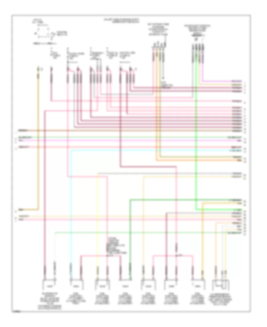
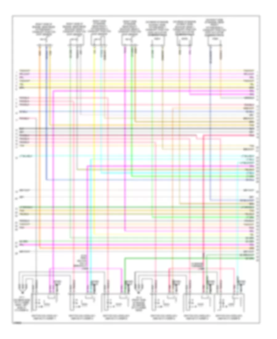
3.6L VIN 7, Engine Performance Wiring Diagram (1 of 6) for Chevrolet Malibu LTZ 2008
List of elements for 3.6L VIN 7, Engine Performance Wiring Diagram (1 of 6) for Chevrolet Malibu LTZ 2008:
- (on left side of engine comp) underhood fuse block
- 5-volt ref
- Acc
- Acc volt
- Accelerator pedal position (app) sensor (attached to accelerator pedal)
- Air conditioning system
- App sens 1 sig
- App sens 2 sig
- B10
- Batt pos volt
- Body control module (bcm) (under right side of center console)
- C10
- Cluster/ theft fuse 10a
- Clutch rly ctrl
- Computer data lines system
- Cooling fans system
- Driver information center (dic) display
- Ecm fuse 10a
- Ecm ign fuse 16 10a
- Engine control module (ecm) (left side of engine compt, front of battery)
- Evaporative emission (evap) canister vent solenoid valve (behind left side of rear fascia splash shield, behind wheel well)
- Exterior lights system
- F pmp rly ctrl
- Fan rly ctrl
- Fuel lvl sens
- Fuel tank pressure (ftp) sensor (in fuel tank, part of fuel pump & sender assembly)
- G109 (on left rear core support, next to g104)
- G201 (under center console, on right side of front support bracket, next to g203, near bcm)
- Gmlan data
- Gnd
- Hot at all times
- Ign 1 volt
- Ignition switch
- Instrument panel cluster (ipc)
- Logic
- Low ref
- Maf fuse 5 10a
- Main rly ctrl
- Malfunc- tion indicator lamp
- Mil ctrl
- Off
- Pnk
- Power tops system
- Press sens sig
- Rly coil ctrl
- Run
- Run/ crank relay 32
- Start
- Starting/charging system
- Stop lmp sply
- Tan
- Vent sol ctrl
- Vss
3.6L VIN 7, Engine Performance Wiring Diagram (2 of 6) for Chevrolet Malibu LTZ 2008
List of elements for 3.6L VIN 7, Engine Performance Wiring Diagram (2 of 6) for Chevrolet Malibu LTZ 2008:
- (on exhaust manifold) heated oxygen sensor (ho2s) bank 2 sensor 1
- (on left side of engine compt) underhood fuse block
- (on top right side of engine) intake manifold tuning (imt) solenoid valve
- A/c refrigerant pressure sensor (left side of engine compt, mounted on a/ c line)
- A10
- B11
- C11
- Ctrl c
- D11
- Emission 1 fuse 6 10a
- Etc fuse 2 15a
- Evaporative emission (evap) canister purge solenoid valve (top rear of engine, on intake manifold)
- Fuel injector 1 (at number 1 cylinder intake port)
- Fuel injector 2 (at number 2 cylinder intake port)
- Fuel injector 3 (at number 3 cylinder intake port)
- Fuel injector 4 (at number 4 cylinder intake port)
- Fuel injector 5 (at number 5 cylinder intake port)
- Fuel injector 6 (at number 6 cylinder intake port)
- G107 (near tac module)
- Gnd b
- Hot at all times
- Ign a
- Inj/coil even fuse 44 15a
- Inj/coil odd fuse 43 15a
- J107
- J114
- Nca
- Pnk
- Post o2 fuse 45 10a
- Pwr/trn relay 33
- Sig d
- Tan
3.6L VIN 7, Engine Performance Wiring Diagram (3 of 6) for Chevrolet Malibu LTZ 2008
List of elements for 3.6L VIN 7, Engine Performance Wiring Diagram (3 of 6) for Chevrolet Malibu LTZ 2008:
- (on left side of front cylinder head, below throttle actuator control module) engine coolant temperature (ect) sensor
- (on top front of engine, in upper intake manifold) manifold absolute pressure (map) sensor
- (under rear of vehicle, in fuel tank) fuel pump & sender assembly
- 5-volt ref 1
- A/c press sens sig
- A10
- Computer data lines system
- Cooling fans system
- Duty cycle sig
- Ect sens sig
- Emission 2 fuse 5 10a
- Engine control module (ecm) (left side of engine compt, near battery)
- Evap purge sol ctrl
- Fuel level sensor
- Fuel pump
- Fuel pump fuse 25 15a
- Fuel/pmp relay 37
- G301 (under right rear seat back)
- G302 (under left rear seat back, towards door)
- Gen turn on sig
- Gmlan data bus +
- Gmlan data bus -
- Ho2s hi ref bank 2
- Ho2s hi sig bank 2
- Ho2s htr low ctrl
- Ho2s low sig bank 2
- Hot at all times
- Imt valve ctrl
- Low ref
- Low sp fan rly ctrl
- Park/neutral sig
- Pnk
- Rear fuse block (in left side of luggage compt, behind left rear wheel well)
- Starting/ charging system
- Tan
3.6L VIN 7, Engine Performance Wiring Diagram (4 of 6) for Chevrolet Malibu LTZ 2008
List of elements for 3.6L VIN 7, Engine Performance Wiring Diagram (4 of 6) for Chevrolet Malibu LTZ 2008:
- (after catalytic converter) heated oxygen sensor (ho2s) bank 1 sensor 2
- (after catalytic converter) heated oxygen sensor (ho2s) bank 2 sensor 2
- (center of rear exhaust manifold) heated oxygen sensor (ho2s) bank 1 sensor 1
- (front center of engine, above starter) engine oil pressure (eop) switch
- Engine control module (ecm) (left side of engine compt, near battery)
- Imt valve sig
- Knock sensor (ks) 1 (above starter)
- Map sens sig
- Nca
- Oil press sw sig
- Park neutral sig
- Pnk
- Tan
- Throttle actuator control (tac) module (on throttle body)
- Transmission control module (tcm) (inside transmission)
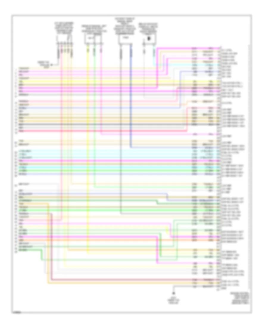
3.6L VIN 7, Engine Performance Wiring Diagram (5 of 6) for Chevrolet Malibu LTZ 2008
List of elements for 3.6L VIN 7, Engine Performance Wiring Diagram (5 of 6) for Chevrolet Malibu LTZ 2008:
- (5 cm from ignition coil 5 breakout) j198
- (in engine harness) j199
- (on rear of engine, on right side) exhaust bank 1 camshaft position (cmp) actuator solenoid valve
- (on rear of engine, on right side) intake bank 1 camshaft position (cmp) actuator solenoid valve
- (on right side of engine, near front) intake bank 2 camshaft position (cmp) actuator solenoid valve
- (right side of engine, near front) exhaust bank 2 camshaft position (cmp) sensor
- (right side of engine, near front) intake bank 2 camshaft position (cmp) sensor
- (right side of engine, near rear) exhaust bank 1 camshaft position (cmp) sensor
- (right side of engine, near rear) intake bank 1 camshaft position (cmp) sensor
- G111 (on rear side of cylinder head, left side at cylinder 5)
- G113 (front side of engine, on center of cylinder head)
- Ignition coil/module 1 (above cylinder 1)
- Ignition coil/module 2 (above cylinder 2)
- Ignition coil/module 3 (above cylinder 3)
- Ignition coil/module 4 (above cylinder 4)
- Ignition coil/module 5 (above cylinder 5)
- Ignition coil/module 6 (above cylinder 6)
- Nca
- Pnk
- Pnk b
- Spark plug
- Tan
3.6L VIN 7, Engine Performance Wiring Diagram (6 of 6) for Chevrolet Malibu LTZ 2008
List of elements for 3.6L VIN 7, Engine Performance Wiring Diagram (6 of 6) for Chevrolet Malibu LTZ 2008:
- (at air cleaner) mass air flow (maf)/intake air temperature (iat) sensor
- (below exhaust manifold, above transaxle) knock sensor (ks) 2
- (near tac module) g107
- (on right side of engine, near front) exhaust bank 2 camshaft position (cmp) actuator solenoid valve
- (rear of engine, left side of block) crankshaft position (ckp) sensor
- 12-v ref
- 5-v ref
- 5-v ref bank 1 exh
- 5-v ref bank 1 int
- 5-v ref bank 2 exh
- 5-v ref bank 2 int
- Ckp sens 1 sig
- Cmp act sol sig
- Cmp sig bank 1 ext
- Cmp sig bank 2 exh
- Cmp sig bank 2 int
- Cmp sol bank 1 exh
- Cmp sol bank 1 int
- Cmp sol bank 2 exh
- Cmp sol bank 2 int
- Engine control module (ecm) (left side of engine compt, near battery)
- Fuel inj 1 ctrl
- Fuel inj 2 ctrl
- Fuel inj 3 ctrl
- Fuel inj 4 ctrl
- Fuel inj 5 ctrl
- Fuel inj 6 ctrl
- G107 (near tac module)
- Gnd
- Ho2s hi sig
- Ho2s htr low ctrl
- Ho2s low sig
- Iat sens sig
- Ic 1 ctrl
- Ic 2 ctrl
- Ic 3 ctrl
- Ic 4 ctrl
- Ic 5 ctrl
- Ic 6 ctrl
- Ign 1 volt
- Ks 1 sig
- Ks 2 sig
- Low ref
- Low ref bank 1 exh
- Low ref bank 1 int
- Low ref bank 2 exh
- Low ref bank 2 int
- Maf sens sig
- Map sens sig
- Pnk
- Tac motor ctrl 1
- Tac motor ctrl 2
- Tan
- Tp sens 1 sig
- Tp sens 2 sig