STARTING/CHARGING
Charging Wiring Diagram for Ford Pickup F150 2008
 https://portal-diagnostov.com/license.html
Automotive Electricians Portal FZCO
Automotive Electricians Portal FZCO
https://portal-diagnostov.com/license.html
https://portal-diagnostov.com/license.html
Automotive Electricians Portal FZCO
Automotive Electricians Portal FZCO
List of elements for Charging Wiring Diagram for Ford Pickup F150 2008:
- Battery
- C102a
- C175b
- C220a
- C220b
- C270f
- Can bus+
- Can bus-
- Central junction box (cjb) (near right 'a' pillar)
- Computer data lines system
- Fuse 5a
- G100 (right rear of engine)
- G101 (right rear of engine compartment)
- G105 (right front of engine compt)
- Gen com
- Gen mon
- Generator
- Hot in run or start
- Instrument cluster
- Powertrain control module (pcm) (right rear of engine compt)
- Red
- S119
- S120
- S121
- S225
- Starting circuit
- Vpwr
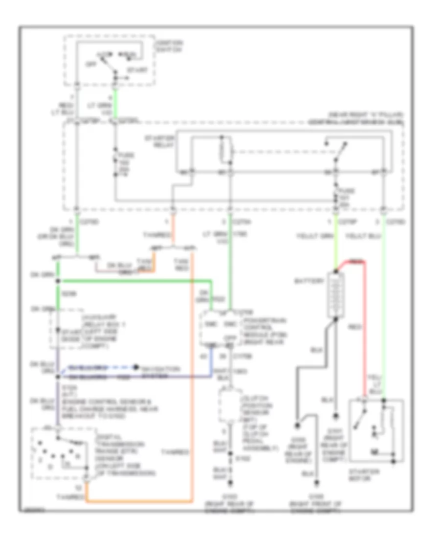
Starting Wiring Diagram for Ford Pickup F150 2008
List of elements for Starting Wiring Diagram for Ford Pickup F150 2008:
- (near right "a" pillar) central junction box (cjb)
- A/t
- Acc
- Auxiliary relay box 1 (left side of engine compt)
- Battery
- C175b
- C270a
- C270d
- C270h
- C270p
- Clutch position sensor (m/t) (top of clutch pedal assembly)
- Cpp bt
- Digital transmission range (dtr) sensor (on left side of transmission)
- Fuse 20a
- Fuse 30a
- G100 (right rear of engine)
- G101 (right rear of engine compt)
- G103 (right rear of engine compt)
- G105 (right front of engine compt)
- Ignition switch
- M/t
- Navigation system
- Off
- Powertrain control module (pcm) (right rear
- Red
- Run
- S102
- S124 (a/t) (engine control sensor & fuel charge harness, near breakout to g102)
- S298
- Smc
- Start
- Start diode
- Starter motor
- Starter relay
- Tan/ red
- Tan/red

 Čeština
 Dansk
Dansk Deutsch
 Ελληνικά
 English
 English
 Suomi
Suomi Français
 Français
 עברית
עברית Hrvatski
 Magyar
 Italiano
 日本語
日本語 한국어
한국어 Nederlands
 Polski
 Português
 Português
 Română
 Русский
 Slovenčina
 Slovenščina
 Svenska
 Türkçe
 中文 (中国)