TRANSMISSION
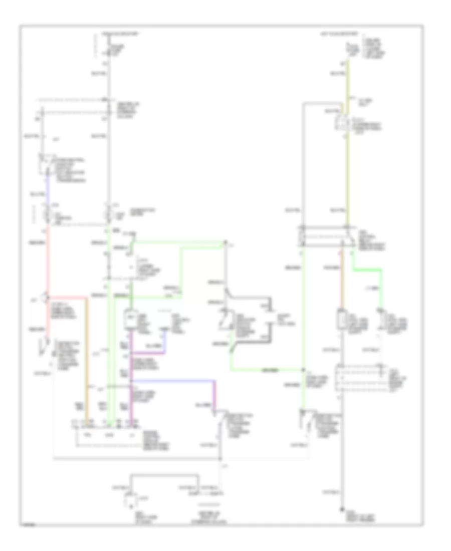
4WD Wiring Diagram, with 2-4 Select Switch for Toyota 4Runner SR5 1998
 https://portal-diagnostov.com/license.html
Automotive Electricians Portal FZCO
Automotive Electricians Portal FZCO
https://portal-diagnostov.com/license.html
https://portal-diagnostov.com/license.html
Automotive Electricians Portal FZCO
Automotive Electricians Portal FZCO
List of elements for 4WD Wiring Diagram, with 2-4 Select Switch for Toyota 4Runner SR5 1998:
- (dash harn, left kick panel) i1
- 2-4
- 2-4 select motor (on transfer case)
- 2-4 select switch
- 2wd
- 4wd
- 4wd ecu (left kick panel)
- 4wd fuse 20a
- 4wd indicator
- A/t
- A/t ind switch
- A/t parking indicator
- A17
- Abs ecu (right kick panel)
- Add indicator switch (middle of engine compt)
- C10
- C11
- C12
- C16
- C19
- Center j/b (right of steering column)
- Detection switch (transfer 4wd position) (transfer case)
- Detection switch (transfer l4 position) (transfer case)
- Detection switch (transfer neutral position) (transfer case)
- Diff lock ecu (left kick panel)
- Driver side j/b (lower left side of dash)
- E11
- E16
- E18
- Engine control module (behind right side of dash)
- Exi
- Exi3
- G100 (front of left front fender)
- G201 (right side of dash)
- Gauge fuse 10a
- Gnd
- Hot in on or start
- I11
- I11 (dash harn, right side of dash)
- I11 (dash harness, upper right side of dash)
- I5 (dash harness, upper left side of dash)
- Ind
- Instrument cluster
- J/c 1 (left front of engine compt)
- J/c 2
- J/c 7
- J/c 8 (upper right side of dash)
- J/c 9
- Park/ neutral position switch
- Pnk
- Rl1
- Rl2
- Spd
- Speedometer
- Tfn
- Vsv (2wd, add) (left side of engine compt)
- Vsv (4wd, add) (left side of engine compt)
- W/ rear diff lock
4WD Wiring Diagram, without 2-4 Select Switch for Toyota 4Runner SR5 1998
List of elements for 4WD Wiring Diagram, without 2-4 Select Switch for Toyota 4Runner SR5 1998:
- (dash harn, right side of dash)
- (dash harn, upper right side of dash)
- (right kick panel)
- (transfer case)
- (upper right side of dash)
- 2.7l
- 3.4l
- 4wd
- 4wd fuse 20a
- 4wd ind
- A/t
- A/t parking ind
- Abs ecu
- Add control relay (behind right side of dash)
- Add indicator switch (middle of engine compt)
- C10
- C11
- C19
- Center j/b (right of steering column)
- Combination meter
- Dash harn, upper right side of dash)
- Dectection switch (transfer 4wd pos) (transfer case)
- Dectection switch (transfer l4 pos) (transfer case)
- Detection switch (transfer neutral position)
- Diff lock ecu (left kick panel)
- Driver side j/b (lower left side of dash)
- E11
- E16
- E18
- Engine control module (behind right side of dash)
- Exi
- Exi3
- G100 (front of left front fender)
- G201 (right side of dash)
- Gauge fuse 10a
- Hot in on or start
- I10 or i11
- I11
- I19
- J/c 2 (left front of engine compt) j/c 1
- J/c 7
- J/c 7 (upper right side of dash) j/c 8
- J/c 8
- J/c 9
- Nca
- Park/neutral position switch (a/t indicator switch) (transmission)
- Short pin (w/o add)
- Tfn
- Vsv (2wd, add) (left side of engine compt)
- Vsv (4wd, add) (left side of engine compt)
- W/ add
- W/ add only
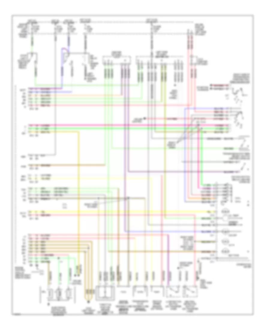
A/T Wiring Diagram for Toyota 4Runner SR5 1998
List of elements for A/T Wiring Diagram for Toyota 4Runner SR5 1998:
- (2.7l)
- (3.4l)
- (3.4l) (2.7l)
- (center of dash) j/c 6
- (left front fender) g100
- (left side of dash) center j/b
- (right side of dash)
- (right side of dash) i11
- (right side of dash) i11 i10 (right side of dash)
- (right side of transmission) park/neutral position switch
- 2.7l
- 3.4l
- A/t p
- Batt
- C10
- C11
- C12
- C15
- C16
- C19
- Combination meter
- Cruise control
- Driver side j/b (lower left side of dash)
- E10
- E11
- E12
- E16
- E18
- E22
- Ect pwr
- Efi
- Efi fuse 15a
- Electronic controlled transmission solenoid
- Engine control module (behind right side of dash)
- Engine coolant
- Engine romm j/b (left inner fender panel)
- Eo1
- Eo2
- Eo3
- G100 (left front fender)
- G202 (left side kick panel)
- G203 (right kick panel)
- Guage fuse 10a
- Hot at all times
- Hot in on or start
- Hot in start
- I10
- I11
- I11 (right side of dash)
- I19
- I20
- Ign fuse 7.5a
- J/c 5 (center of dash)
- L4 detection switch (on transfer case)
- Neutral detection switch (on transfer case)
- Nsw
- O/d main switch (below center console)
- O/d off
- Od1
- Od2
- Oil
- Oil temp
- Oil-w
- Pwr
- Relay (in engine room j/b)
- Sol
- Sp1
- Sp2+
- Sp2-
- Speedo- meter
- Sta fuse 7.5a
- Starting/ charging
- Stop fuse 10a
- Stop light switch (above brake pedal)
- Temperature sensor (rear of engine)
- Tfn
- Throttle position sensor (on throttle body)
- Thw
- Transmission fluid temperature sensor (on trans)
- Transmission pattern select switch (center console)
- Vehicle speed sensor (on trans)
- Vta
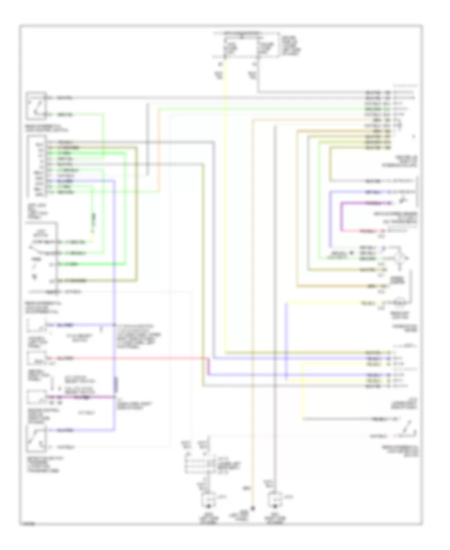
Rear Differential Lock Wiring Diagram for Toyota 4Runner SR5 1998
List of elements for Rear Differential Lock Wiring Diagram for Toyota 4Runner SR5 1998:
- (under left rear seat) j/c 12
- 2.7l w/o 2-4 select switch
- 3.4l, 2.7l w/ 2-4 select switch
- 4wd
- 4wd ecu (left kick panel)
- 4wd fuse 20a
- A/t only
- A17
- Abs ecu (3.4l only)
- Abs ecu (right kick panel)
- C10
- C11
- C12
- C14
- C16
- Center j/b (right of steering column)
- Combination meter
- Detection switch (transfer l4 position) (transfer case)
- Diff lock ecu (left kick panel)
- Driver side j/b (lower left side of dash)
- E14
- E16
- E18
- Engine control module (right side of dash)
- Exi2
- Free
- G200 (left kick panel)
- G201 (right side of dash)
- G202 (left side of dash)
- Gauge fuse 10a
- Gnd
- Hot in on or start
- I11 (dash harn, right side of dash)
- I11 (w/o 2-4 switch) i1 (w/ 2-4 switch) (i10: dash harn, upper right side of dash) (i1: dash harn, left kick panel)
- J/c 13
- J/c 4
- J/c 7
- J/c 8 (upper right side of dash)
- J/c 9
- Limit switch
- Lock
- Rear diff lock ind
- Rear differential lock control switch
- Rear differential lock detection switch
- Rear differential lock motor (on differential)
- Rel1
- Rel2
- Rlp
- Rly1
- Rly2
- Spd
- Speed- ometer
- Vehicle speed sensor (2.7l only) (on transmission)
- W/ 2-4 select switch
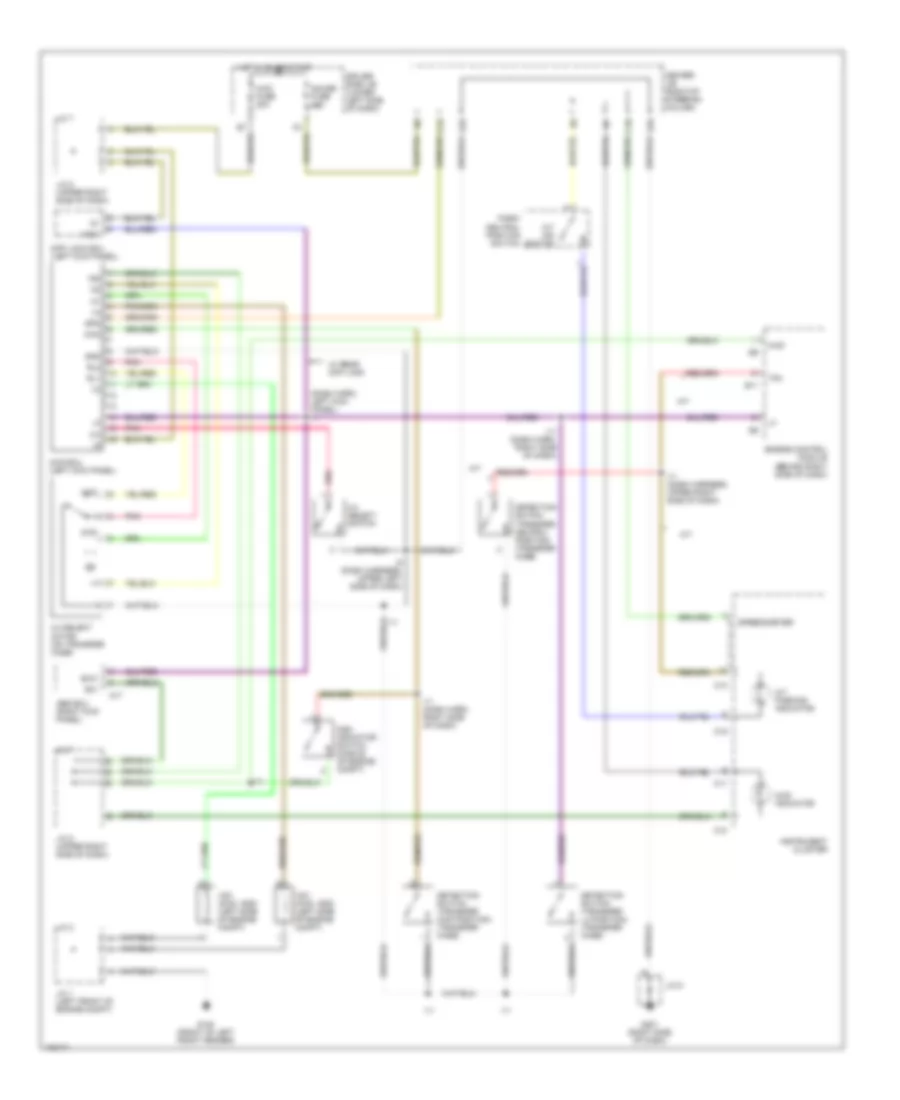
Transfer Case Wiring Diagram, with 2-4 Select Switch for Toyota 4Runner SR5 1998
List of elements for Transfer Case Wiring Diagram, with 2-4 Select Switch for Toyota 4Runner SR5 1998:
- (dash harn, left kick panel) i1
- 2-4
- 2-4 select motor (on transfer case)
- 2-4 select switch
- 2wd
- 4wd
- 4wd ecu (left kick panel)
- 4wd fuse 20a
- 4wd indicator
- A/t
- A/t ind switch
- A/t parking indicator
- A17
- Abs ecu (right kick panel)
- Add indicator switch (middle of engine compt)
- C10
- C11
- C12
- C16
- C19
- Center j/b (right of steering column)
- Detection switch (transfer 4wd position) (transfer case)
- Detection switch (transfer l4 position) (transfer case)
- Detection switch (transfer neutral position) (transfer case)
- Diff lock ecu (left kick panel)
- Driver side j/b (lower left side of dash)
- E11
- E16
- E18
- Engine control module (behind right side of dash)
- Exi
- Exi3
- G100 (front of left front fender)
- G201 (right side of dash)
- Gauge fuse 10a
- Gnd
- Hot in on or start
- I11
- I11 (dash harn, right side of dash)
- I11 (dash harness, upper right side of dash)
- I5 (dash harness, upper left side of dash)
- Ind
- Instrument cluster
- J/c 1 (left front of engine compt)
- J/c 2
- J/c 7
- J/c 8 (upper right side of dash)
- J/c 9
- Park/ neutral position switch
- Pnk
- Rl1
- Rl2
- Spd
- Speedometer
- Tfn
- Vsv (2wd, add) (left side of engine compt)
- Vsv (4wd, add) (left side of engine compt)
- W/ rear diff lock
Transfer Case Wiring Diagram, without 2-4 Select Switch for Toyota 4Runner SR5 1998
List of elements for Transfer Case Wiring Diagram, without 2-4 Select Switch for Toyota 4Runner SR5 1998:
- (dash harn, right side of dash)
- (dash harn, upper right side of dash)
- (right kick panel)
- (transfer case)
- (upper right side of dash)
- 2.7l
- 3.4l
- 4wd
- 4wd fuse 20a
- 4wd ind
- A/t
- A/t parking ind
- Abs ecu
- Add control relay (behind right side of dash)
- Add indicator switch (middle of engine compt)
- C10
- C11
- C19
- Center j/b (right of steering column)
- Combination meter
- Dash harn, upper right side of dash)
- Dectection switch (transfer 4wd pos) (transfer case)
- Dectection switch (transfer l4 pos) (transfer case)
- Detection switch (transfer neutral position)
- Diff lock ecu (left kick panel)
- Driver side j/b (lower left side of dash)
- E11
- E16
- E18
- Engine control module (behind right side of dash)
- Exi
- Exi3
- G100 (front of left front fender)
- G201 (right side of dash)
- Gauge fuse 10a
- Hot in on or start
- I10 or i11
- I11
- I19
- J/c 2 (left front of engine compt) j/c 1
- J/c 7
- J/c 7 (upper right side of dash) j/c 8
- J/c 8
- J/c 9
- Nca
- Park/neutral position switch (a/t indicator switch) (transmission)
- Short pin (w/o add)
- Tfn
- Vsv (2wd, add) (left side of engine compt)
- Vsv (4wd, add) (left side of engine compt)
- W/ add
- W/ add only

 Čeština
 Dansk
Dansk Deutsch
 Ελληνικά
 English
 English
 Suomi
Suomi Français
 Français
 עברית
עברית Hrvatski
 Magyar
 Italiano
 日本語
日本語 한국어
한국어 Nederlands
 Polski
 Português
 Português
 Română
 Русский
 Slovenčina
 Slovenščina
 Svenska
 Türkçe
 中文 (中国)