TRANSMISSION
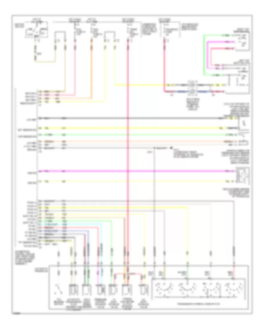
3.8L VIN 2
3.8L VIN 2, A/T Wiring Diagram for Pontiac Grand Prix GTP 2005
 https://portal-diagnostov.com/license.html
Automotive Electricians Portal FZCO
Automotive Electricians Portal FZCO
https://portal-diagnostov.com/license.html
https://portal-diagnostov.com/license.html
Automotive Electricians Portal FZCO
Automotive Electricians Portal FZCO
List of elements for 3.8L VIN 2, A/T Wiring Diagram for Pontiac Grand Prix GTP 2005:
- (tfc) sender
- (vin 2: on top right of intake manifold) (vin 4: top left rear of engine) engine coolant temperature sensor
- 1-2 shift solenoid valve
- 2-3 shift solenoid valve
- 5 volt ref
- Acc
- At iss sig
- Automatic transaxle
- Automatic transmission fluid temperature
- Battery
- Cruise sw fuse 2a
- D11
- E12
- Ect sensor sig
- G113 (lower right front of engine, on transaxle stud, near starter)
- Ground
- Hot at all times
- Hot in run or start
- I/p fuse block (behind right side of dash)
- Ignition 1
- Ignition 3
- Ignition switch
- Inflatable restraint steering wheel coil module
- Input shaft speed sensor
- Left tap shift switch
- Lock
- Low ref
- Manifold absolute pressure (map) sensor (vin 2: top right side of intake manifold) (vin 4: top right rear of engine)
- Map sensor sig
- Off
- Oss sig
- Pc sol
- Pcm fuse 15 10a
- Pcm/ etc fuse 16 15a
- Pnk
- Pnk b
- Powertrain control module (left front side of engine compt, in air cleaner assembly)
- Pressure control solenoid valve
- Red
- Remote shift
- Right tap shift switch
- S101
- S115
- S201
- Shift sol a
- Shift sol b
- Start
- Tan
- Tap dn
- Tap up
- Tcc release switch
- Tcc sol
- Tcc sw sig
- Tft sensor sig
- Torque converter clutch solenoid valve
- Tr sw a
- Tr sw b
- Tr sw c
- Tr sw p
- Trans sol fuse 21 10a
- Transmission internal mode switch
- Underhood fuse block (mounted to right strut tower)
- Vehicle speed sensor (lower right side of engine compt, on transaxle)
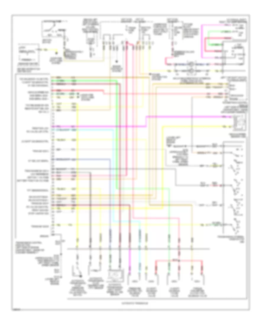
3.8L VIN 4
3.8L VIN 4, A/T Wiring Diagram for Pontiac Grand Prix GTP 2005
List of elements for 3.8L VIN 4, A/T Wiring Diagram for Pontiac Grand Prix GTP 2005:
- (tfc) sender
- (vin 2: on top right of intake manifold) (vin 4: top left rear of engine) engine coolant temperature sensor
- 1-2 shift solenoid valve
- 2-3 shift solenoid valve
- 5 volt ref
- Acc
- At iss sig
- Automatic transaxle
- Automatic transmission fluid temperature
- Battery
- Cruise sw fuse 2a
- D11
- E12
- Ect sensor sig
- G113 (lower right front of engine, on transaxle stud, near starter)
- Ground
- Hot at all times
- Hot in run or start
- I/p fuse block (behind right side of dash)
- Ignition 1
- Ignition 3
- Ignition switch
- Inflatable restraint steering wheel coil module
- Input shaft speed sensor
- Left tap shift switch
- Lock
- Low ref
- Manifold absolute pressure (map) sensor (vin 2: top right side of intake manifold) (vin 4: top right rear of engine)
- Map sensor sig
- Off
- Oss sig
- Pc sol
- Pcm fuse 15 10a
- Pcm/ etc fuse 16 15a
- Pnk
- Pnk b
- Powertrain control module (left front side of engine compt, in air cleaner assembly)
- Pressure control solenoid valve
- Red
- Remote shift
- Right tap shift switch
- S101
- S115
- S201
- Shift sol a
- Shift sol b
- Start
- Tan
- Tap dn
- Tap up
- Tcc release switch
- Tcc sol
- Tcc sw sig
- Tft sensor sig
- Torque converter clutch solenoid valve
- Tr sw a
- Tr sw b
- Tr sw c
- Tr sw p
- Trans sol fuse 21 10a
- Transmission internal mode switch
- Underhood fuse block (mounted to right strut tower)
- Vehicle speed sensor (lower right side of engine compt, on transaxle)
5.3L VIN C
5.3L VIN C, A/T Wiring Diagram for Pontiac Grand Prix GTP 2005
List of elements for 5.3L VIN C, A/T Wiring Diagram for Pontiac Grand Prix GTP 2005:
- (behind left side of dash, left steering column) body control module (bcm)
- (lower left rear of engine) g115
- (steering column harness) s240
- (w/ manual shift) right tap shift switch
- 1-2 shift solenoid (1-2 ss) valve
- 1-2 shift solenoid ctrl
- 2-3 shift solenoid (2-3 ss) valve
- 2-3 shift solenoid ctrl
- Acc
- At iss high signal
- At iss low signal
- Automatic transaxle
- Automatic transmission fluid pressure (tfp) manual valve position switch
- Automatic transmission fluid temperature (tft) sensor
- Automatic transmission input shaft speed (at iss) sensor
- Battery positive voltage
- Bus +
- Bus -
- Computer data lines system
- Cruise sw fuse 2a
- Driver information center (dic)
- E12
- Ecm/tcm fuse 1 15a
- Engine controls system
- Front sig high
- Front sig low
- G115 (lower left rear of engine)
- Gmlan data bus +
- Gmlan data bus -
- Ground
- Hot at all times
- Hot in on or start
- I/p fuse block (behind right side of dash, in glove box opening)
- Ign vol 3
- Ignition 1 voltage
- Ignition switch
- Inflatable restraint steering wheel module coil (in steering column)
- Left tap shift switch (w/ manual shift)
- Lock
- Logic
- Low reference
- Message center
- Nca
- P/n sig
- Pc valve high ctrl
- Pc valve low ctrl
- Pnk
- Power distribution system
- Powertrain control module (left side of engine compartment, inside air cleaner assembly)
- Pressure control (pc) solenoid valve
- Prnd321
- R p
- Red
- Remote shft sel sig
- Run
- S115
- S125 (approximately 5 cm from breakout to left front wheel speed sensor)
- Sae serial bus +
- Sae serial bus -
- Serial data
- Start
- Stop lamp sw
- Stop lamp sw sig
- Tan
- Tap
- Tap dn
- Tap down
- Tap up
- Tcc release sw sig
- Tcc solenoid valve ctrl
- Tft sensor signal
- Torque converter clutch (tcc) solenoid valve
- Tran range sw sig a
- Tran sw sig c
- Trans fuse 10a
- Trans sw sig b
- Trans sw sig p
- Transmission control module (tcm) (left side of engine compartment, inside air cleaner assembly)
- Transmission internal mode switch (ims)
- Underhood fuse block (mounted to right strut tower)
- Vehicle sig
- Vehicle speed sensor (vss)
- Vehicle speed sig

 Čeština
 Dansk
Dansk Deutsch
 Ελληνικά
 English
 English
 Español
 Suomi
Suomi Français
 עברית
עברית Hrvatski
 Magyar
 Italiano
 日本語
日本語 한국어
한국어 Nederlands
 Polski
 Português
 Português
 Română
 Русский
 Slovenčina
 Slovenščina
 Svenska
 Türkçe
 中文 (中国)