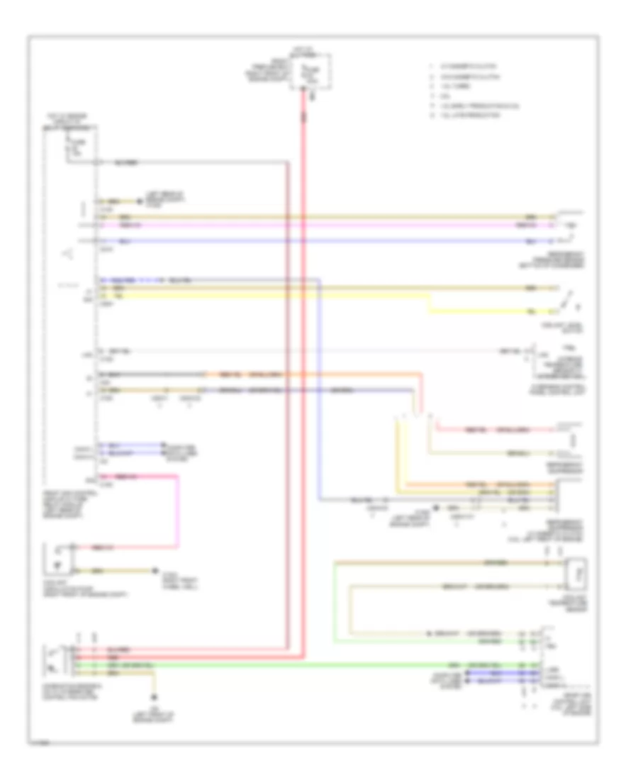
COOLING FAN
Cooling Fan Wiring Diagram for Mercedes-Benz SLK250 2014
List of elements for Cooling Fan Wiring Diagram for Mercedes-Benz SLK250 2014:
- (left rear of engine compt) w16/5
- 1.8l early production & 3.5l
- 1.8l late production
- 1.8l turbo
- 3.5l
- C13d
- C14m
- C18m
- C20m
- C21m
- C2i
- C3m
- Can-c h
- Can-c l
- Combustion engine & a/c w/ integrated control fan motor
- Computer data lines system
- Coolant circulation pump (right front of engine compt)
- Coolant level switch
- Coolant temperature sensor
- Front prefuse box (right front of engine compt)
- Front sam control module w/ fuse/ relay module (left rear of engine compt)
- Fuse 100a
- Fuse 15a
- Hot at all times
- Hot w/ engine circuit 87 relay energized
- Interior temperature sensor w/ integrated fan
- Lin2
- Lues
- Me-sfi (me) control unit (3.5l: left side of engine)
- Mr1
- Overhead control panel control unit
- Red
- Refrigerant compressor
- Refrigerant compressor w/ magnetic clutch (3.5l: left front of engine)
- Refrigerant pressure sensor (bottom of condenser)
- Sig
- Tem
- W/ magnetic clutch
- W/o magnetic clutch
- W16/4 (right front wheel well)
- W16/5 (left rear of engine compt)
- W9 (left front of engine compt)
- X25/2-c2
- X26-c1
- X26/21-c1
 Čeština
 Dansk
Dansk Deutsch
 Ελληνικά
 English
 English
 Español
 Suomi
Suomi Français
 עברית
עברית Hrvatski
 Magyar
 Italiano
 日本語
日本語 한국어
한국어 Nederlands
 Polski
 Português
 Português
 Română
 Русский
 Slovenčina
 Slovenščina
 Svenska
 Türkçe
 中文 (中国)
 Français