ENGINE PERFORMANCE
3.2L
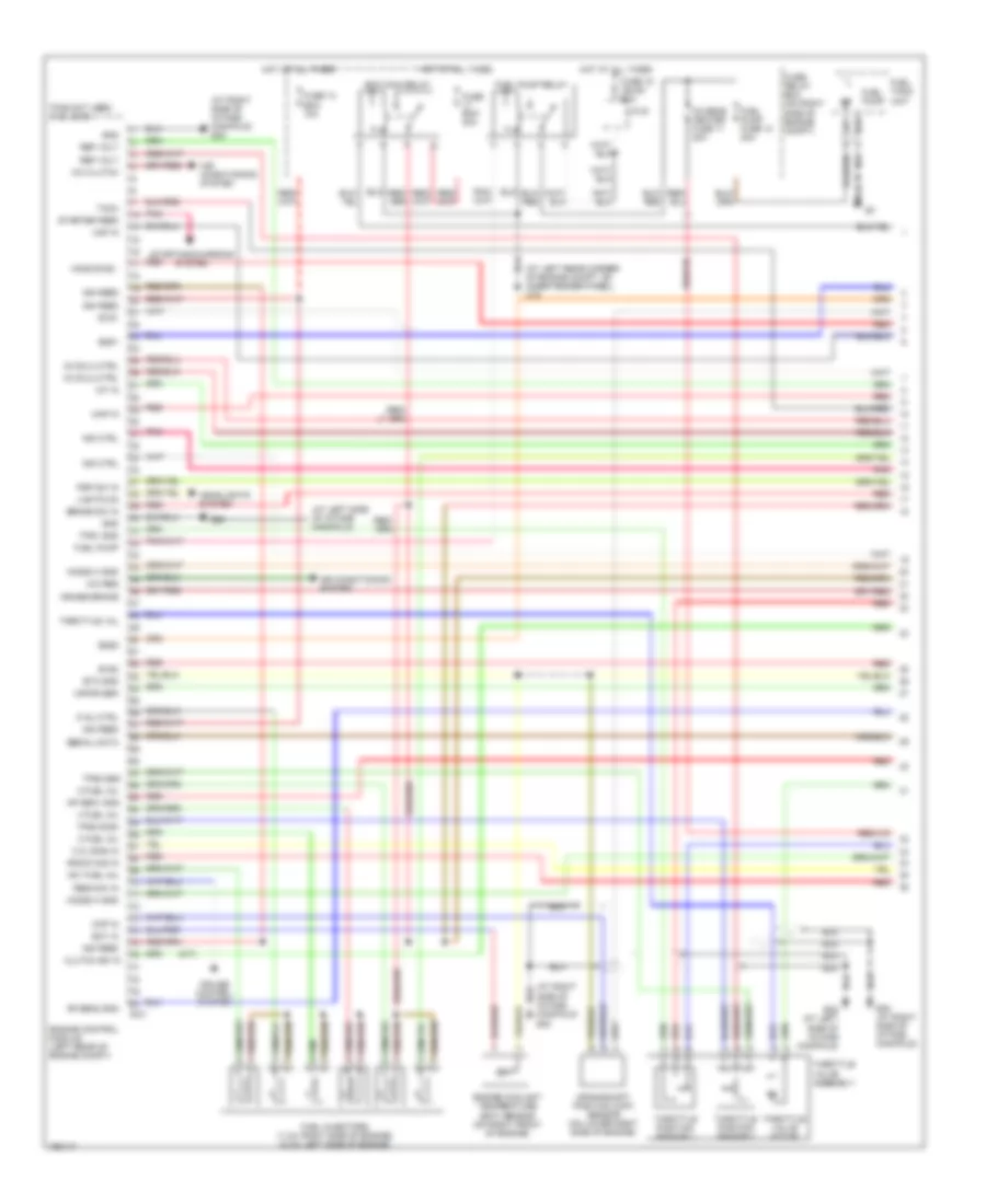
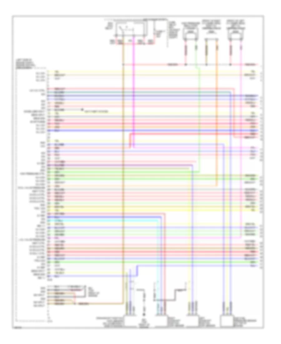
3.2L, Engine Performance Wiring Diagram (1 of 4) for Isuzu Rodeo S 2004
List of elements for 3.2L, Engine Performance Wiring Diagram (1 of 4) for Isuzu Rodeo S 2004:
- (at left rear corner of engine compt, on inner fender panel) c16
- (at left side of intake manifold)
- (at right side of intake manifold) e30
- (m/t)
- 2 fuel inj
- 3 fuel inj
- 4 fuel inj
- 5 inj ctrl
- A/c clutch
- A/c req
- Air conditioning system
- Ap sen1 gnd
- Ap sen2 gnd
- B1s1
- B1s2
- B2s1
- B2s2
- Brake sw in
- C.q. sign in
- Ckp in
- Clutch sw in
- Crankshaft position (ckp) sensor (on lower right side of engine)
- Cruise brake
- Cruise control system
- E-21
- E28
- E28 (at left side of intake manifold)
- E30 (at right side of intake manifold)
- Ecm main relay
- Ect in
- Engine control module (left rear of engine compt)
- Engine coolant temperature (ect) sensor (on right front of engine)
- Etc gnd
- Fuel injectors (1,3,5: right side of engine) (2,4,6: left side of engine)
- Fuel pump
- Fuel pump fuse 12 20a
- Fuel pump relay
- Fuel tank unit
- Fuse 13 ecm 10a
- Fuse 15 ign b1 60a
- Fuse ecm 30a
- Fuse/ relay box (on right side of engine compt)
- Gnd
- Headlights system
- Ho2s b1s2 -
- Ho2s2 h gnd
- Hot at all times
- Iat in
- Ig coil2 ctrl
- Ig coil3 ctrl
- Ign feed
- Ind ctrl
- J/c b
- Knock sig in
- Lights on
- Maf in
- Map in
- N01 fuel inj
- O2 sens heater fuse 11 20a
- Pins not used: 8-12, 35-36
- Pnk
- Psp sw in
- Red
- Ref volt
- Res/acc in
- Serial data
- Starter feed
- Starting/charging system
- Tach
- Throttle position sensor 1
- Throttle position sensor 2
- Throttle val
- Throttle valve assembly
- Throttle valve motor
- Tps1 gnd
- Tps2 gnd
- Tps2 sign
- Vapor sen
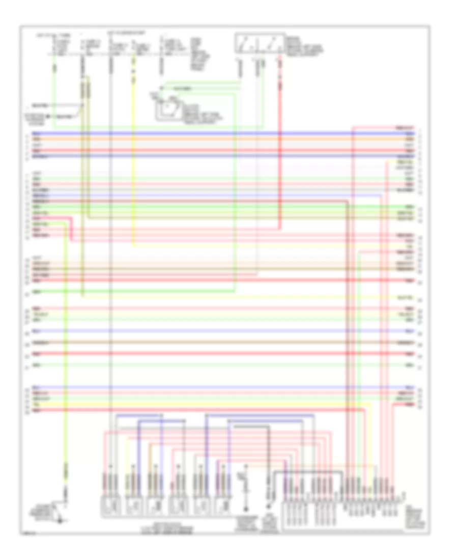
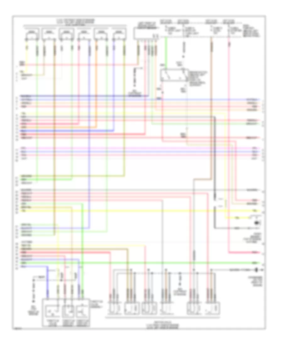
3.2L, Engine Performance Wiring Diagram (2 of 4) for Isuzu Rodeo S 2004
List of elements for 3.2L, Engine Performance Wiring Diagram (2 of 4) for Isuzu Rodeo S 2004:
- 1,3,5 coil in
- 2,4,6 coil in
- Brake switch (behind left side of dash, on brake pedal support)
- Clutch switch (behind left side of dash, on clutch pedal support)
- Coil 1 ctrl
- Coil 2 ctrl
- Coil 3 ctrl
- Coil 4 ctrl
- Coil 5 ctrl
- Coil 6 ctrl
- Condenser (0n right front of condenser)
- Dash fuse box (behind left side of dash, behind panel)
- E-16
- E-17
- E-18
- E29 (at left side of intake manifold)
- Est 11
- Est 12
- Est 13
- Est 21
- Est 22
- Est 23
- Fuse 11 meter 15a
- Fuse 12 engine ig 15a
- Fuse 13 ig coil 15a
- Fuse 14 back up/ turn light 15a
- Fuse 6 stop light 15a
- Gnd
- Hot at all times
- Hot in on or start
- Ign
- Ignition coils (1,3,5: right side of engine) (2,4,6: left side of engine)
- Ion sensing module (on top of intake manifold)
- Ioncq1
- Ionk1
- Pnk
- Power steering pressure switch
- Red
- Starting/ charging system
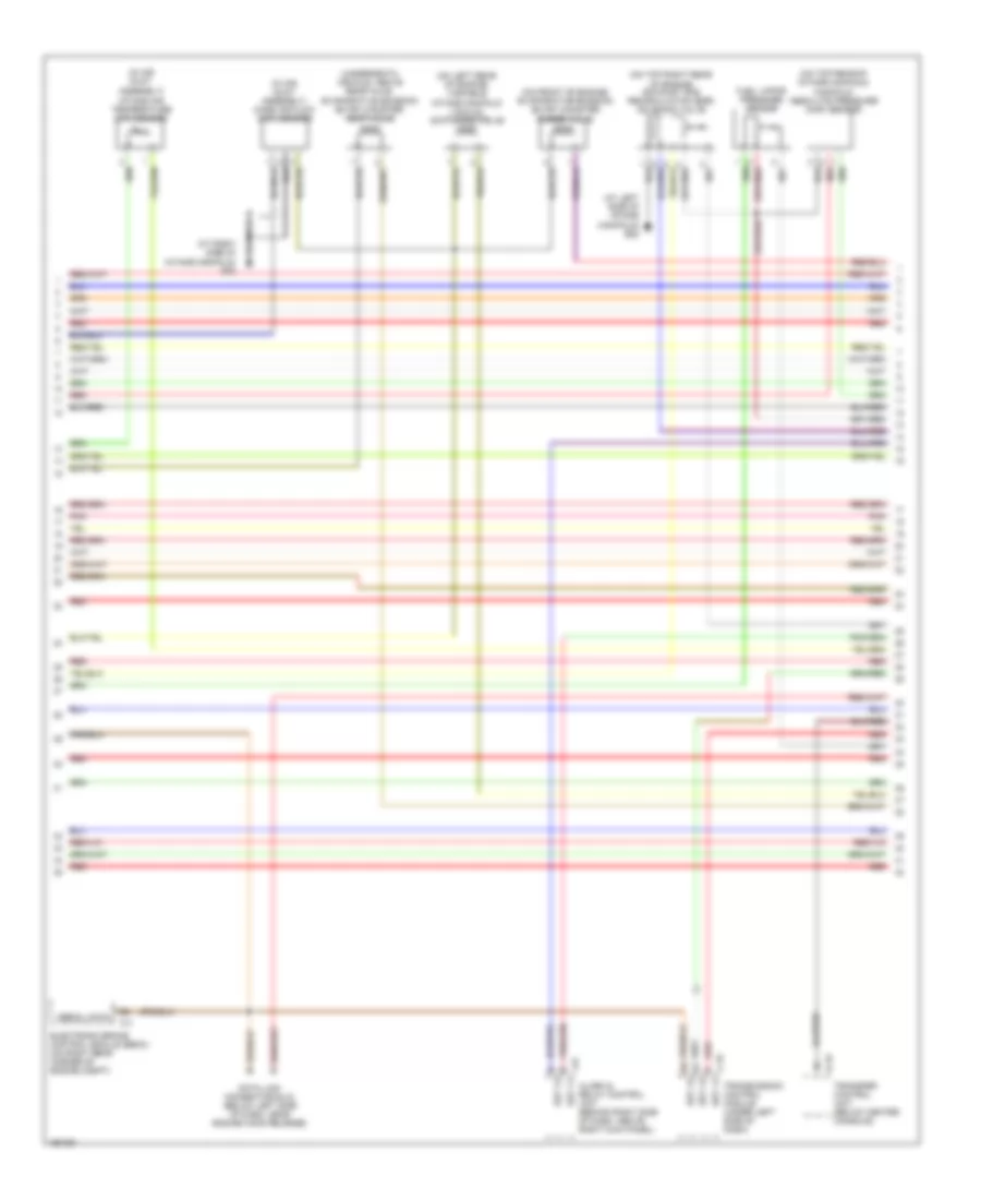
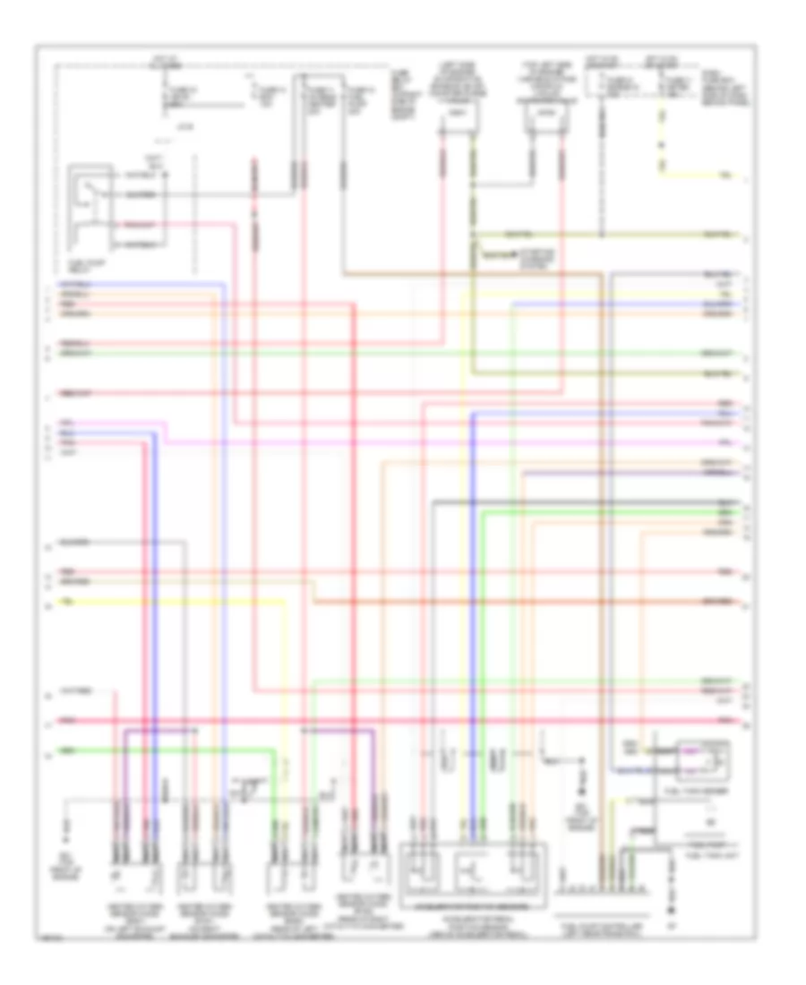
3.2L, Engine Performance Wiring Diagram (3 of 4) for Isuzu Rodeo S 2004
List of elements for 3.2L, Engine Performance Wiring Diagram (3 of 4) for Isuzu Rodeo S 2004:
- (at left side of intake manifold) e28
- (in air duct assembly) intake air temperature (iat) sensor
- (in air duct assembly) mass air flow (maf) sensor
- (on front of engine) evaporative emission (evap) canister purge valve
- (on left rear of engine) variable intake manifold vacuum switching valve
- (on top rear of intake manifold) manifold absolute pressure (map) sensor
- (on top right rear of engine) exhaust gas recirculation (egr) solenoid valve
- (underneath vehicle, above rear axle) evaporative emission (evap) canister vent valve
- Alarm & relay control unit (behind right side of dash, above right kick panel)
- B-19
- C-4
- C-78
- Data link connector (dlc) (below left side of dash, near engine hood release)
- Electronic brake control module (ebcm) (on right rear corner of engine compt)
- Est 11
- Est 12
- Est 13
- Fuel vapor pressure sensor
- I-42
- Pnk
- Red
- Serial data
- Transfer control unit (below center console)
- Transmission control module (under left side of dash)
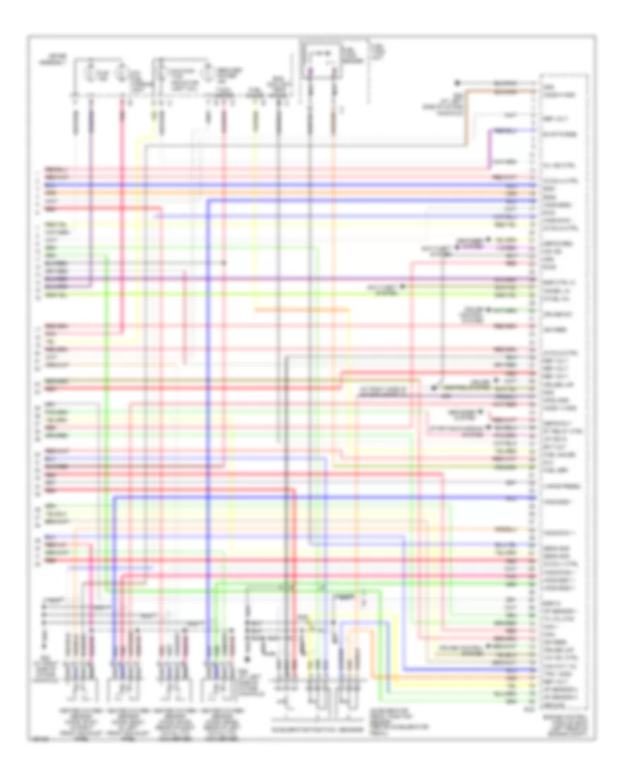
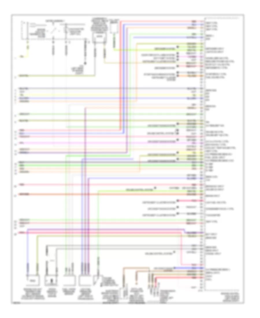
3.2L, Engine Performance Wiring Diagram (4 of 4) for Isuzu Rodeo S 2004
List of elements for 3.2L, Engine Performance Wiring Diagram (4 of 4) for Isuzu Rodeo S 2004:
- "u/s" ind
- (at right side of intake manifold)
- 6 fuel inj
- Accelerator pedal position sensor (above accelerator pedal)
- Accelerator positioin sensors
- Anti-theft system
- Ap sensor 1
- Ap sensor 2
- Ap sensor 3
- Aps3 gnd
- B1s1
- B1s2
- B2s1
- B2s2
- Can +
- Can cut val
- Can-
- Cruise control system
- Cruise lmp
- Cruise sw
- Defog req
- Defog rly
- Defogger system
- Defogger sysyem
- Dlc
- E-22
- E28 (at left side of intake manifold)
- E30
- E30 (at right side of intake manifold)
- Ect out
- Egr ctrl hi
- Egr in
- Eng coolant temp gauge
- Engine control module (ecm) (left rear of engine compt)
- Evap purge
- F-1
- Fuel gauge
- Fuel sen
- Fuel tank sender
- Fuel tank unit
- Gnd
- Ground
- Heated oxygen sensor (ho2s) (b1s1) (in right front exhaust pipe)
- Heated oxygen sensor (ho2s) (b1s2) (rear of right catalytic converter)
- Heated oxygen sensor (ho2s) (b2s1) (in left front exhaust pipe)
- Heated oxygen sensor (ho2s) (b2s2) (rear of left catalytic converter)
- Ho2s b1s1 +
- Ho2s b1s1 -
- Ho2s b1s2 +
- Ho2s b2s1 +
- Ho2s b2s1 -
- Ho2s b2s2 +
- Ho2s b2s2 -
- Ho2s1 h gnd
- Ho2s1h gnd
- I-1
- I-2
- I-9
- Ig coil1 ctrl
- Ig coil4 ctrl
- Ig coil5 ctrl
- Ig coil6 ctrl
- Ign feed
- Imm ind
- Immobil in
- Low fuel warning light
- Malfunc- tion indicator light (mil)
- Meter assembly
- Mil ind ctrl
- Nca
- Pnk
- Red
- Reduced power ind
- Ref volt
- Sens gnd
- St relay ctrl
- Starting/charging system
- Tach- ometer
- Th val mtr
- Tps 1 sign
- Up ind in
- Vapor press
- Vim vsv ctrl
3.5L
3.5L, Engine Performance Wiring Diagram (1 of 4) for Isuzu Rodeo S 2004
List of elements for 3.5L, Engine Performance Wiring Diagram (1 of 4) for Isuzu Rodeo S 2004:
- (front of left cylinder head) left oil control valve
- (front of right cylinder head) right oil control valve
- (left side of engine compt) engine control module (ecm)
- 5v ref
- Anti-theft system
- C-74
- Crankshaft position (ckp) sensor (on lower right side of engine)
- E-48
- E21 (top front of engine)
- Ecm main relay
- Evap purge
- Fuse-17 ecm 30a
- Fuse/ relay box (on right side of engine compt)
- Gnd
- Heat ctrl
- High fuel pressure sensor (on top of engine)
- High pressure ctrl
- High pressure regulator valve
- Hot in on or start
- Ig coil1 ctrl
- Ig coil2 ctrl
- Ig coil3 ctrl
- Ig coil4 ctrl
- Ig coil5 ctrl
- Ig coil6 ctrl
- Ign input
- Immobilizer input
- Inj high
- Inj low
- L oil valve pressure
- Left camshaft position (cmp) sensor
- Nca
- Pnk
- R oil valve pressure
- Red
- Rev (+)
- Rev (-)
- Right camshaft position (cmp) sensor
- Sens gnd
- Sens input
- Sig
- Tps 1 sig
- Tps 2 sig
- Vcc
- Vim vcv ctrl
3.5L, Engine Performance Wiring Diagram (2 of 4) for Isuzu Rodeo S 2004
List of elements for 3.5L, Engine Performance Wiring Diagram (2 of 4) for Isuzu Rodeo S 2004:
- (1,3,5: top right side of engine) (2,4,6: top left side of engine) fuel injectors
- (left front of engine compt) maf/iat sensor
- Brake switch (behind left side of dash, on brake pedal support)
- Condenser (on top front of engine)
- Dash fuse box (behind left side of dash, behind panel)
- E21 (top front of engine)
- E23 (top front of engine)
- Fuse-13 ig coil 15a
- Fuse-14 back-up/ turn light 15a
- Fuse-3 starter 10a
- Fuse-6 stop light 15a
- Hot in on or start
- Iat
- Ignition coils (1,3,5: right side of engine) (2,4,6: left side of engine)
- Knock sensor 1 (top of engine)
- Nca
- Pnk
- Red
- Throttle position sensor 1
- Throttle position sensor 2
- Throttle valve assembly
- Throttle valve motor
3.5L, Engine Performance Wiring Diagram (3 of 4) for Isuzu Rodeo S 2004
List of elements for 3.5L, Engine Performance Wiring Diagram (3 of 4) for Isuzu Rodeo S 2004:
- (left side of engine) evaporative emission (evap) canister purge valve
- (top left side of engine) variable intake manifold vacuum switching valve
- Accelerator pedal position sensor (above accelerator pedal)
- Accelerator position sensors
- Dash fuse box (behind left side of dash, behind panel)
- E21 (top front of engine)
- Fuel pump
- Fuel pump controller (left rear frame rail)
- Fuel pump relay
- Fuel tank sender
- Fuel tank unit
- Fuse-11 meter 15a
- Fuse-11 o2 sens, heater 20a
- Fuse-12 engine ig 15a
- Fuse-12 fuel pump 20a
- Fuse-13 ecm 10a
- Fuse-15 ign b1 60a
- Fuse/ relay box (on right side of engine compt)
- Heated oxygen sensor (ho2s) (b1s1) (on right exhaust downpipe)
- Heated oxygen sensor (ho2s) (b1s2) (rear of right catalytic converter)
- Heated oxygen sensor (ho2s) (b2s1) (on left exhaust downpipe)
- Heated oxygen sensor (ho2s) (b2s2) (rear of left catalytic converter)
- Hot at all times
- Hot in on or start
- J/c b
- Nca
- Pnk
- Red
- Starting/ charging system
3.5L, Engine Performance Wiring Diagram (4 of 4) for Isuzu Rodeo S 2004
List of elements for 3.5L, Engine Performance Wiring Diagram (4 of 4) for Isuzu Rodeo S 2004:
- (underneath vehicle, above rear axle) evaporative emission (evap) canister vent valve
- 5v ref
- A/c clutch rly ctrl
- A/c pressure sens (-)
- A/c pressure sens (5v)
- A/c pressure sens (vcc)
- A/c request sig
- Air conditioning system
- Anti-theft system
- B6 serial data
- Brake input
- Brake sw input
- C-4
- C-74
- C-78
- C16 (left rear of engine compt)
- Can-h
- Can-l
- Cancel input
- Canl-h
- Canl-l
- Computer data lines system
- Condenser fan rly ctrl
- Coolant temp gauge ctrl
- Cruise control system
- Cruise ind ctrl
- Cruise on input
- Cruise set ind ctrl
- Data link connector (dlc) (below left side of dash, near engine hood release)
- Defogger input
- Defogger rly ctrl
- Defogger system
- Ecm main rly ctrl
- Ect input
- Electronic brake control module (ebcm) (on right rear corner of engine compt)
- Engine control module (ecm) (left side of engine compt)
- Engine coolant temperature (ect) sensor (on rear of engine, in coolant manifold)
- Engine coolant temperature gauge
- Evap cut valve ctrl
- Fuel gauge ctrl
- Fuel level input
- Fuel vapor pressure sensor
- Gnd
- Heat ctrl
- I-1
- I-2
- Ign
- Immobilizer ind ctrl
- Instrument cluster system
- J1850
- Knock sensor 2 (top of engine)
- Lights on input
- Low fuel ind ctrl
- Low fuel pressure sensor (left side of transmission)
- Malfunction indicator light (mil)
- Meter assembly
- Nca
- Pnk
- Power steering pressure (psp) switch
- Red
- Reduced power ind ctrl
- Sens (-)
- Sens (vcc)
- Sens gnd
- Sens input
- Sens sig
- Serial data
- Sig
- Starter rly ctrl
- Starting/charging system
- Tachometer
- Taillight relay
- Transmission control module (under left side of dash)
- Vcc

 Čeština
 Dansk
Dansk Deutsch
 Ελληνικά
 English
 English
 Español
 Suomi
Suomi Français
 עברית
עברית Hrvatski
 Magyar
 Italiano
 日本語
日本語 한국어
한국어 Nederlands
 Polski
 Português
 Português
 Română
 Русский
 Slovenčina
 Slovenščina
 Svenska
 Türkçe
 中文 (中国)