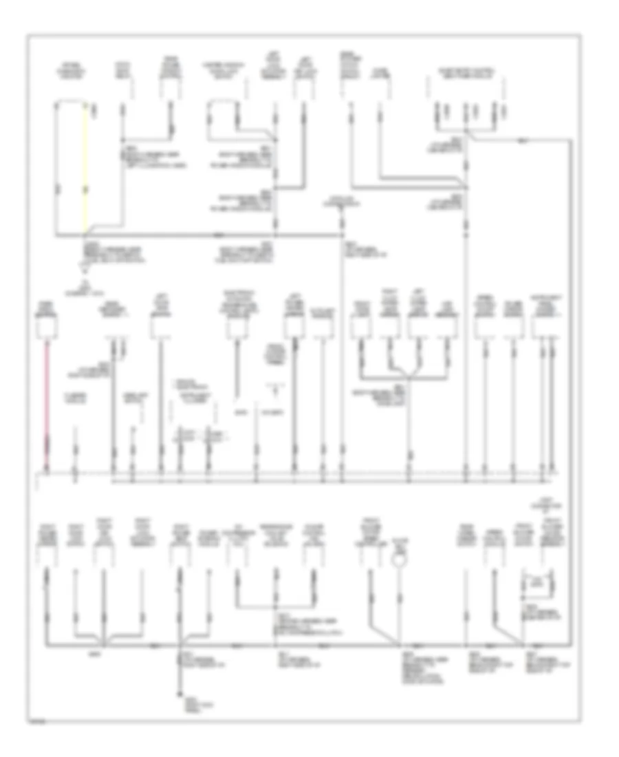
GROUND DISTRIBUTION
Ground Distribution Wiring Diagram (1 of 3) for Mercury Villager Nautica 1997

List of elements for Ground Distribution Wiring Diagram (1 of 3) for Mercury Villager Nautica 1997:
- (engine harness, near breakout to a/c compressor clutch)
- (engine harness, near breakout to left front park/turn lamp) s105
- (engine harness, near breakout to pcm)
- (engine harness, right side of i/p) s214
- (front of left front fender)
- (i/p harness, near breakout to refresh/ recirculate door actuator)
- (i/p harness, right side of i/p)
- (left front of engine compartment)
- (left front of engine)
- (right rear of engine compartment, on strut tower)
- A/c high pressure switch
- Accessory relay
- Anti-lock brake control module
- Battery
- Brake fluid level switch
- Bulb check relay
- C134
- C135
- C136
- Camshaft position sensor
- Camshaft position sensor shield
- Cooling fan motor
- Crankshaft position sensor shield
- Data link connector #1
- Data link connector #2
- Daytime running lamps module
- Engine compartment fuse/relay panel
- Engine compartment fuse/relay panel junction connector #2
- From s202 (diagram 2 of 3)
- From s212 (diagram 3 of 3)
- Front heated oxygen sensor
- Front wiper motor assembly
- G100
- G102 (left rear of engine compartment, on side of strut tower)
- G103
- G103 (right rear of engine compartment, on side of strut tower)
- G106
- G108
- G111 (left side of engine compartment, below battery tray)
- G134 (top of engine)
- G200 (left kick panel)
- G201 (behind right side of i/p)
- Generator/ voltage regulator
- Hood switch
- I/p fuse/relay panel
- Ignition key switch
- Ignition relay
- Inhibit relay
- Knock sensor shield
- Left front marker lamp
- Left front park/ cornering lamp
- Left front turn lamp
- Left front wheel speed sensor shield
- Left headlamp
- Left headlamp relay
- Left rear wheel speed sensor shield
- Mass air flow sensor shield
- Nca
- Not used
- O/d off switch
- Outside air temperature sensor
- Power transistor
- Powertrain control module
- Rear heated oxygen (ho2s) sensor
- Rear heated oxygen sensor shield
- Resistor shield
- Right front marker lamp
- Right front park/ cornering lamp
- Right front turn lamp
- Right front wheel speed sensor shield
- Right headlamp (w/o drl)
- Right headlamp relay
- Right rear wheel speed sensor shield
- S100 (engine harness, inside engine compt relay box)
- S101 (engine harness, near breakout to right headlamp)
- S102 (engine harness, near breakout to engine oil pressure switch)
- S103 (engine harness, near breakout to right headlamp)
- S104 (engine harness, near breakout to left front park/turn lamp)
- S106
- S107 (engine harness, near breakout to wiper/washer amplifier assembly)
- S108
- S109
- S110
- S117
- S117 (engine harness, near breakout to left front park/turn lamp)
- S200 (engine harness, near breakout inertia fuel shut-off switch)
- S213 (engine harness, right rear eng compt)
- S215 (engine harness, near breakout to g201)
- S216 (engine harness, near breakout to abs module)
- S218 (engine harness, right rear of engine)
- S219 (engine harness, right rear of engine)
- S220
- S221 (engine harness, near breakout to tcm)
- S222 (engine harness, near breakout to pcm)
- S230
- Shield
- Shift lock solenoid/ park position switch
- Speed control hold relay
- Throttle position sensor shield
- To g415 (diagram 3 of 3)
- Transaxle control module
- Washer fluid level switch
- Wiper/washer amplifier assembly
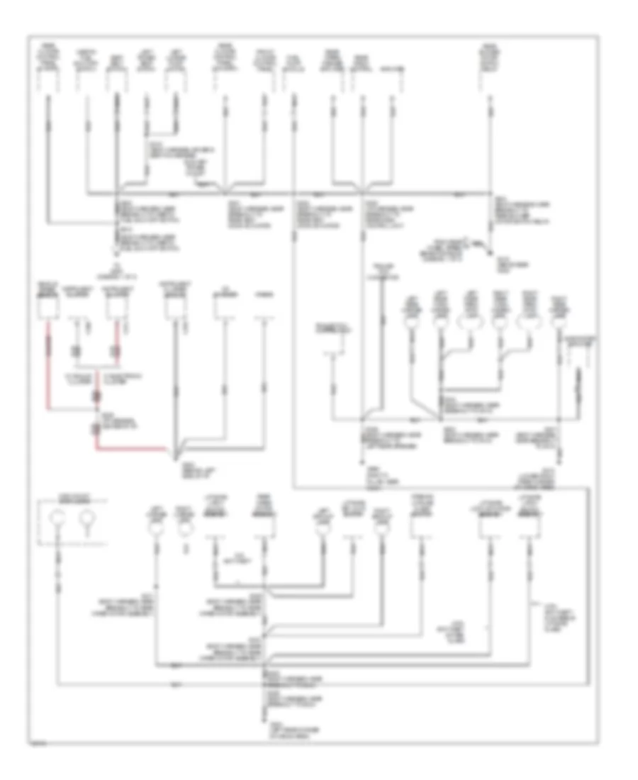
Ground Distribution Wiring Diagram (2 of 3) for Mercury Villager Nautica 1997
List of elements for Ground Distribution Wiring Diagram (2 of 3) for Mercury Villager Nautica 1997:
- * analog ** electronic
- * **
- A/c
- Air bag
- Autolamp module
- Blower
- Blower motor/ speed controller
- Box lamp
- C2003
- C2030
- C2031
- C2032
- C266
- C270
- C274
- C276
- Cigar lighter
- Compressor clutch coil
- Control (iac) valve #1
- Control module
- Coolant valve solenoid
- Data link connector #1
- Diagnostic monitor
- Door jamb switch
- Door lock switch
- Eatc
- Electronic automatic
- Flasher module
- Front
- Front blower
- Front climate control panel
- Front dome lamp
- G203 (right kick panel)
- Glove
- Headlamp switch
- Idle air
- Inated visor mirror
- Instrument cluster
- Instrument panel dimmer switch
- Joint connector #1
- Key lock switch
- Left
- Left door
- Left illum-
- Lock actuator assembly
- Lock switch
- Map lamp assembly
- Master window/
- Moon
- Motor
- Motor resistor assembly
- Motor switch
- Nca
- Power antenna module
- Power mirror switch
- Power seat switch
- Power window control
- Power/ heated mirror
- Rear
- Rear blower
- Rear defogger switch
- Rear engine
- Rear radio control
- Right
- Right door
- Right illum-
- Roof relay
- S201 (body harness, near breakout to inertia fuel shut-off switch)
- S203 (i/p harness, right side of i/p)
- S204 (i/p harness, right side of i/p)
- S205 (i/p harness, center of i/p)
- S207 (i/p harness, behind right top side of i/p)
- S208 (i/p harness, behind right top side of i/p)
- S209 (i/p harness, near breakout to refresh/ recirculation door actuator)
- S210 (engine harness, near breakout to a/c compressor clutch)
- S211 (i/p harness, right side of i/p)
- S243 (i/p harness, center of i/p)
- S248 (i/p harness, center of i/p)
- S500 (body harness, near breakout to power window module)
- S501 (body harness, near breakout to power window module)
- S606
- S900 (body harness, near breakout to left illumination visor)
- S901 (body harness, near breakout to dome lamp)
- Smart entry control (sec)/timer module
- Speed
- Speed control on/off switch
- Switch (front)
- Temperature control (eatc) module
- To g200 (diagram 1 of 3)
- W/o eatc
- Wiper/ washer switch
Ground Distribution Wiring Diagram (3 of 3) for Mercury Villager Nautica 1997
List of elements for Ground Distribution Wiring Diagram (3 of 3) for Mercury Villager Nautica 1997:
- (body harness, near breakout to rear wiper motor assembly)
- (right d pillar, near roof)
- Amplifier
- Anti-theft
- Auxiliary power outlet
- Breakout to g404)
- C268
- C270
- C274
- Cd changer
- From rear wheel speed sensor shields (diagram 1 of 3)
- Front climate control panel
- Fuel pump module
- Fuel shut-off switch)
- G202 (behind left side of i/p)
- G404 (left rear corner of cargo area)
- G410 (lower right rear corner of cargo area)
- G415 (above rear axle)
- G998
- High mount stop lamps
- Inertia fuel shut-off switch
- Instrument cluster
- Instrument cluster (analog)
- Lamp
- Left backup lamp
- Left license lamp
- Left lumbar pump motor
- Left power seat switch
- Left rear marker lamp
- Left rear park/ stop lamp
- Left rear turn/ hazard lamp
- Liftgate key lock switch
- Liftgate latch switch assembly
- Liftgate lock actuator assembly
- Nca
- Opening liftgate glass switch
- Radio
- Rear blower motor switch relay
- Rear climate control panel (w/ eatc)
- Rear climate control panel (w/o eatc)
- Rear radio control
- Rear wiper motor assembly
- Rear wiper/ washer amplifier
- Right backup lamp
- Right license lamp
- Right rear marker lamp
- Right rear park/ stop lamp
- Right rear turn/ hazard
- S212
- S229 (i/p harness, center of i/p)
- S301 (body harness, near breakout to rear vent door actuator)
- S302 (body harness, near breakout to rear vent door actuator)
- S304 (body harness, near breakout to rear blower motor switch relay)
- S306 (body harness, near breakout to g404)
- S319 (body harness, driver's seat p/a harness)
- S320 (i/p harness, near breakout to rear radio control unit)
- S336 (body harness, near breakout to left rear speaker)
- S400 (body harness, near breakout to g410)
- S401 (body harness, near breakout to g410)
- S404
- S405 (body harness, near breakout to rear wiper motor assembly)
- S410 (body harness, near breakout to g410)
- S411 (body harness, near breakout to rear wiper motor assembly)
- Seat belt switch
- Subwoofer amplifier
- To g200 (diagram 1 of 3)
- Trailer tow connector
- Trailer tow control unit
- Vehicle speed sensor
- W/ analog cluster
- W/ electronic cluster
- W/o
- With anti-theft & fixed glass
- With anti-theft & moveable liftgate glass