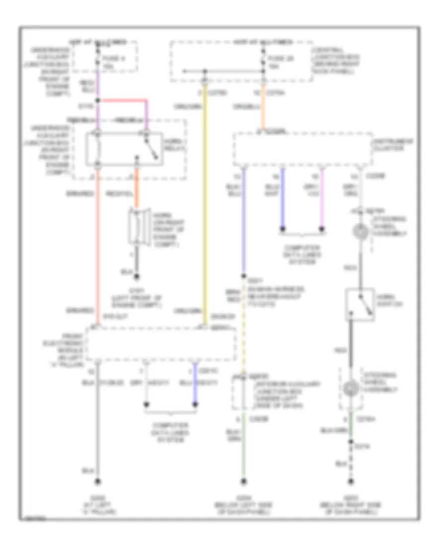
AUTOMOTIVE ELECTRICIANS PORTAL

HORN – Ford Thunderbird 2004 – SYSTEM WIRING DIAGRAMS

HORN

Horn Wiring Diagram for Ford Thunderbird 2004

Horn Wiring Diagram for Ford Thunderbird 2004 https://portal-diagnostov.com/license.html
https://portal-diagnostov.com/license.html Automotive Electricians Portal FZCO Automotive Electricians Portal FZCO
Pridobite dostop do vseh električnih shem avtomobilaDownload PDF file

List of elements for Horn Wiring Diagram for Ford Thunderbird 2004:

  • 10a
  • 15a
  • 29-dk20
  • 91s-gj7
  • C201c
  • C218a
  • C220b
  • C270a
  • C270d
  • C283b
  • C283d
  • Central junction box (behind right kick panel)
  • Computer data lines system
  • Front electronic module (in left ``a" pillar)
  • Fuse 20
  • Fuse 4
  • G101 (left front of engine compt)
  • G202 (at left ``a" pillar)
  • G203 (below right side of dash panel)
  • G204 (below left side of dash panel)
  • Horn switch
  • Horn (on right front of engine compt)
  • Horn relay
  • Hot at all times
  • Instrument cluster
  • Interior auxiliary junction box (under left side of dash)
  • Nca
  • Near breakout to c213)
  • S110
  • S201
  • S214
  • Steering wheel assembly
  • Underhood auxiliary junction box (in right front of engine compt)