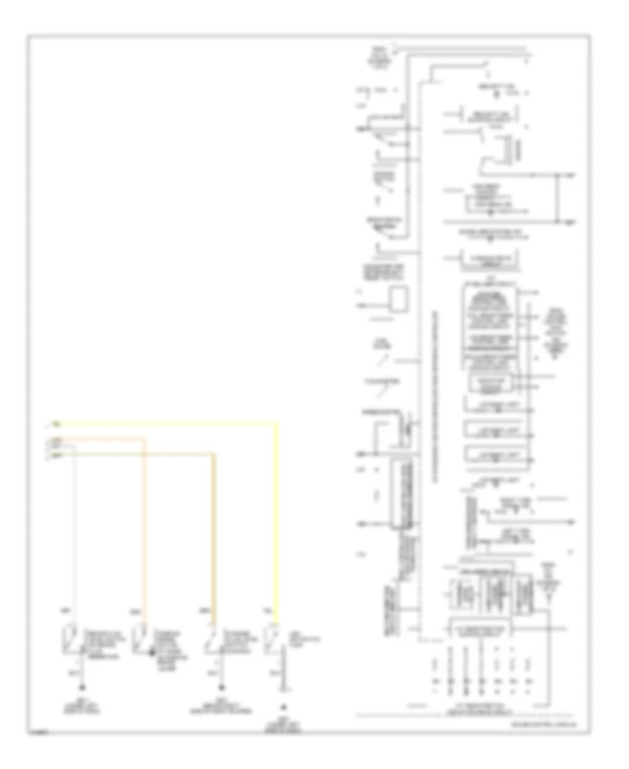
INSTRUMENT CLUSTER
Instrument Cluster Wiring Diagram (1 of 2) for Honda Fit 2009
 https://portal-diagnostov.com/license.html
Automotive Electricians Portal FZCO
Automotive Electricians Portal FZCO
https://portal-diagnostov.com/license.html
https://portal-diagnostov.com/license.html
Automotive Electricians Portal FZCO
Automotive Electricians Portal FZCO
List of elements for Instrument Cluster Wiring Diagram (1 of 2) for Honda Fit 2009:
- micu
- +b back up
- 10a
- 5v stabilizer circuit/controller area network controller
- 7.5a
- Abs ind
- Activation ind
- B-can
- Brake system ind
- Center console, in fuel tank)
- Charging system ind
- Compulsory
- Computer data lines system
- Coolant high temperature ind
- Coolant low
- Cruise control ind
- Cruise control main switch ind
- Cruise control system
- Door open ind
- Drl ind
- Eps ind
- Exterior lights system
- Fog light ind
- Fuel gauge sending unit
- Fuel tank unit (under rear of
- Fuse1
- Fuse22
- G501 (under left side of dash)
- Gauge control module
- Hot at all times
- Hot in on or start
- Ig1 meter
- Interior lights system
- Lights on ind
- Low fuel ind
- Low oil pressure ind
- Low tire pressure ind
- Maintenance required ind
- Mil ind
- Pnk
- Red
- Seat belt reminder ind
- Side airbag cut-off ind
- Srs ind
- Temperature ind
- To indicator dimming circuit (diagram 2 of 2)
- To security ind (diagram 2 of 2)
- Tpms ind
- Turning off circuit (diagram 2 of 2)
- Under-dash fuse/relay box (under left end of dash)
- Vsa malfunction
- Vsa off ind
- Warning drive circuit
- Washer fluid level ind
Instrument Cluster Wiring Diagram (2 of 2) for Honda Fit 2009
List of elements for Instrument Cluster Wiring Diagram (2 of 2) for Honda Fit 2009:
- -off circuit turning
- 10v stabilizer circuit
- 5v stabilizer circuit/controller area network controller
- A/t gear position indicator drive circuit
- A/t gear position dimming circuit
- Beeper
- Body controller area network transceiver
- Brake fluid level switch (on brake fluid reservoir)
- Brightening switch
- Circuit
- Compulsory
- Dial brightness control and dimming circuit
- Dimming switch
- Display (mid) unit multi-information
- Drive warning
- Fail-safe
- From cruise control main switch ind (diagram 1 of 2)
- From mil ind (diagram 1 of 2)
- From pin 16 (diagram 1 of 2)
- Fuel gauge
- G201 (behind right side of front bumper)
- G401 (under left side of dash)
- G501 (under left side of dash)
- Gauge control module
- High beam dimming circuit
- High beam ind
- Immobilizer system ind
- Indicator dimming circuit
- Lcd back light
- Lcd brightness control and dimming circuit
- Left turn signal ind
- Lever)
- Network transceiver fast controller area
- Odometer/trip meter/select/ reset switch
- Parking brake switch (at base of parking brake
- Pointer brightness control and dimming circuit
- Relay 2 (sounder) turn signal/hazard
- Right turn signal ind
- Scale brightness control and dimming circuit
- Security ind
- Security ind blinking circuit
- Speedometer
- Tachometer
- Turning -on circuit
- Unit 5v control
- Vsa off switch (vsa)
- Warning drive circuit
- Washer fluid level switch (canada)

 Čeština
 Dansk
Dansk Deutsch
 Ελληνικά
 English
 English
 Español
 Suomi
Suomi Français
 Français
 עברית
עברית Hrvatski
 Italiano
 日本語
日本語 한국어
한국어 Nederlands
 Polski
 Português
 Português
 Română
 Русский
 Slovenčina
 Slovenščina
 Svenska
 Türkçe
 中文 (中国)