INSTRUMENT CLUSTER
Instrument Cluster Wiring Diagram (1 of 2) for Ford Aerostar 1996

List of elements for Instrument Cluster Wiring Diagram (1 of 2) for Ford Aerostar 1996:
- (behind center of i/p, below right side of radio)
- (behind left side of i/p, near top of
- (behind right
- (below rear of vehicle, top of
- 4 wheel
- Acc
- Air bag diagnostic module (behind left side of i/p, near top of cowl panel)
- Air bag ind.
- Amp ind.
- Amplifier
- Anti- slosh module
- Bat
- Battery ground
- Brake ind.
- C231
- C249
- C250
- C251
- C268
- Chime module
- Column)
- Coolant temp. gauge
- Cowl panel)
- Daytime running lamps module (front of left fender apron, forward of starter relay)
- Door ajar ind.
- Drive module (under right side of left
- Electronic
- Electronic 4 wheel drive ind.
- Enable
- Enable psom programming connector (behind right cowl panel)
- Engine coolant temperature sender (3.0l-top center front of engine) (4.0l-top right front of engine)
- Engine oil pressure switch (3.0l-top right rear of engine, behind valve cover) (4.0l-lower left front of engine, above engine oil pan)
- Fasten belts ind.
- Front seat)
- Fuel gauge
- Fuel pump/fuel
- Fuel tank)
- Fuse 10a
- Fuse 15a
- Fuse 5a
- Fuse panel (behind left side side of i/p, left of steering
- G206
- Gauge sender
- Generator speed control
- Gnd
- High beam ind.
- Hot at all times
- Hot in run
- Hot w/ lamp sw in park or head
- Ign
- Ign (run)
- Ignition switch
- Illumination lamps
- Instrument cluster
- Left turn ind.
- Lock
- Malfunction ind.
- Multi- function switch (top left side of steering column)
- Odometer select
- Off
- Ohms
- Oil press. gauge
- Panel)
- Programming
- Psom module
- Rear abs ind.
- Red/ lt
- Red/pnk
- Right turn ind.
- Run
- Side of i/p, above cowl
- Start
- Trip reset
- Volt- meter
- Voltage regulator (top right front of engine)
- Vss input
- Vss output
- Vss return
- Warning
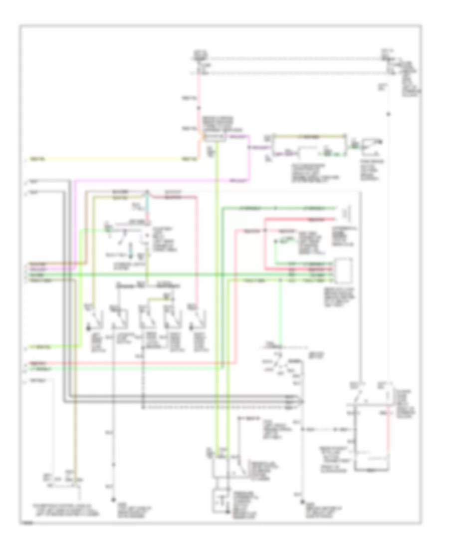
Instrument Cluster Wiring Diagram (2 of 2) for Ford Aerostar 1996
List of elements for Instrument Cluster Wiring Diagram (2 of 2) for Ford Aerostar 1996:
- "b" pillar)
- (front of sliding door)
- (left rear corner of cargo area)
- (rear of right
- (top left side of safety wall,
- Acc
- Brake fluid level switch (on brake master cylinder)
- Brake warning resistor/diode (taped to main harness, near g206)
- Button connectors
- Courtesy lamp relay
- Daytime running lamps module (front of left fender apron, forward of starter relay)
- Differential speed sensor (top of rear axle)
- Dss test connector (left rear of engine compt, on safety wall)
- Fuse
- Fuse 15a
- Fuse panel (behind left side of i/p, left of steering column)
- G100 (left front fender apron, left of battery)
- G206 (behind center of i/p, below left side of radio)
- G406 (top left side of rear door/lift gate header)
- Gnd
- Hot in acc or run
- Hot in run or start
- Ignition switch
- Interior lights system
- Left front door ajar switch
- Left of brake master cylinder)
- Liftgate ajar switch
- Lock
- Off
- Park brake
- Powertrain control module
- Pressure differential warning switch (below brake fluid reservoir)
- Rear anti-lock brake module (behind center of i/p, below ash tray)
- Rear door latch switch
- Red
- Red/pnk
- Right front door ajar switch
- Right rear door ajar switch
- Run
- Sliding door ajar relay (right of steering column)
- Start
- Switch (on park brake support)
- W/ drl
- W/ dual rear doors
- W/ liftgate
- W/o drl