ANTI-THEFT
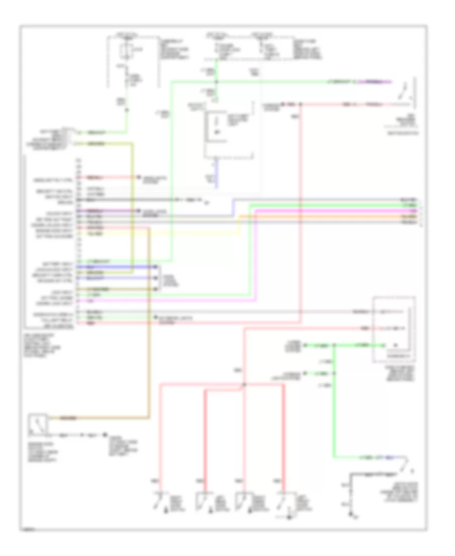
Forced Entry Wiring Diagram (1 of 2) for Isuzu Rodeo S 2004
List of elements for Forced Entry Wiring Diagram (1 of 2) for Isuzu Rodeo S 2004:
- Act pos locked
- Act pos unlocked
- Anti- theft fuse 23 10a
- Anti-theft horn (on right rear corner of engine compartment)
- Anti-theft indicator light
- Battery input
- C36/p6 (at right side of engine compt, behind battery)
- Dash fuse box (behind left side of dash, behind panel)
- Diode box 5
- Disarm lock input
- Disarm unlock input
- Door locks system
- Door/hatch open in
- Dr door act ctrl
- Engine hood input
- Engine hood switch (at right rear corner of engine compt)
- Exterior lights system
- Fuse/relay box (on right side of engine compartment)
- Ground
- Hatch gate open switch (inside top center of tailgate, on latch assembly)
- Headlight rly ctrl
- Headlights system
- Horn fuse 2 10a
- Hot at all times
- Hot in acc or on
- Ignition input
- Ignition switch
- Interior lights system
- J/c b
- Key in ignition
- Key reminder switch
- Key rod act posit
- Keyless entry & anti-theft control unit (behind right side of dash, above kick panel)
- Left front door switch
- Left rear door switch
- Lock input
- Lock/unlock input
- Power door lock fuse 7 20a
- Red
- Right front door switch
- Right rear door switch
- Security horn ctrl
- Security ind ctrl
- Switch unit a
- Taillight relay
- Unlock input
- Warning system
- Wiper/ washer system
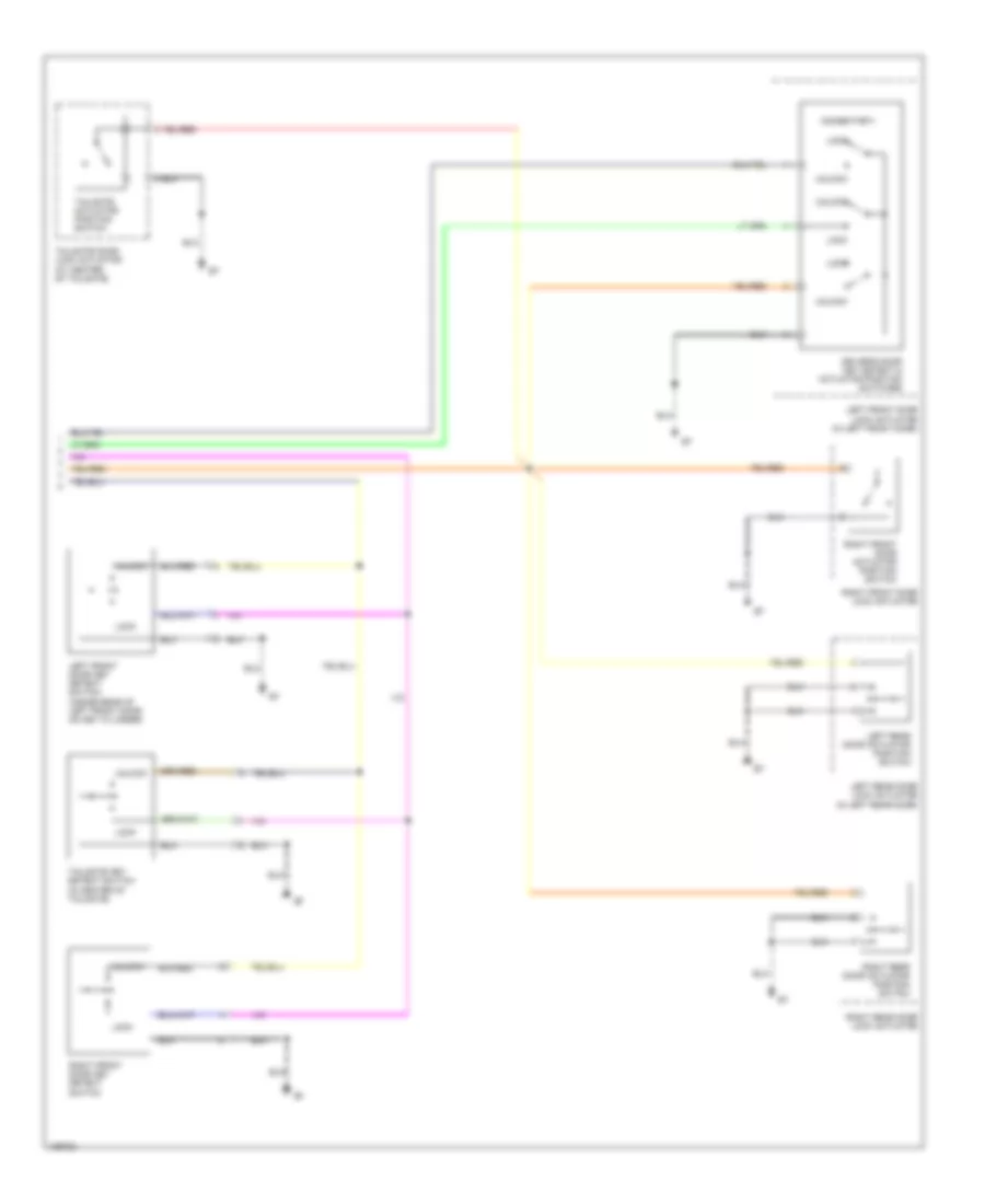
Forced Entry Wiring Diagram (2 of 2) for Isuzu Rodeo S 2004
List of elements for Forced Entry Wiring Diagram (2 of 2) for Isuzu Rodeo S 2004:
- (momentary)
- Driver's door key detect & actuator position switches
- Left front door key detect switch (inside rear of left front door, on key cylinder)
- Left front door lock actuator (in left front door)
- Left rear door actuator position switch
- Left rear door lock actuator (in left rear door)
- Lock
- Right front door actuator position switch
- Right front door key detect switch
- Right front door lock actuator
- Right rear door actuator position switch
- Right rear door lock actuator
- Tailgate actuator position switch
- Tailgate door lock actuator (at center of tailgate)
- Tailgate key detect switch (in center of tailgate)
- Unlock
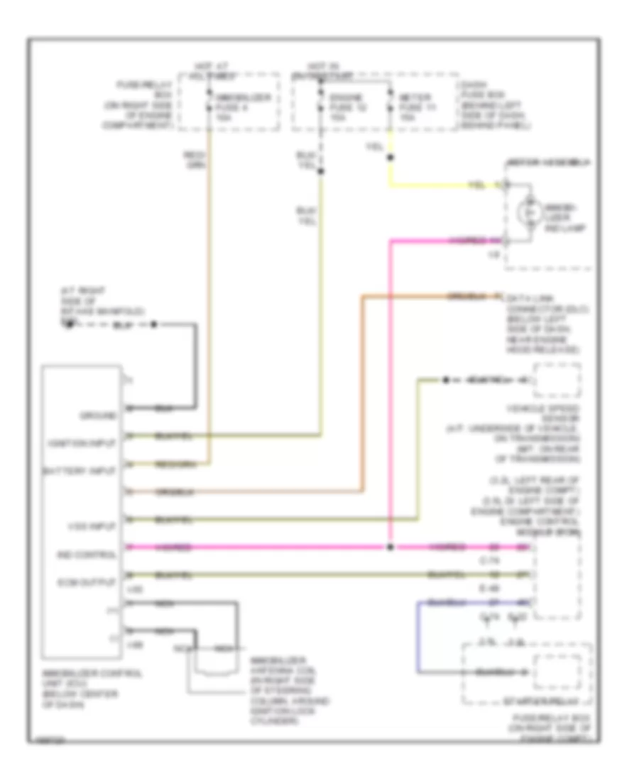
Immobilizer Wiring Diagram for Isuzu Rodeo S 2004
List of elements for Immobilizer Wiring Diagram for Isuzu Rodeo S 2004:
- (+)
- (-)
- (3.2l: left rear of engine compt) (3.5l di: left side of engine compartment) engine control module (ecm)
- (at right side of intake manifold) e30
- 3.2l
- 3.5l
- Battery input
- C-74
- Dash fuse box (behind left side of dash, behind panel)
- Data link connector (dlc) (below left side of dash, near engine hood release)
- E-22
- E-48
- Ecm output
- Engine fuse 12 15a
- Fuse/relay box (on right side of engine compartment)
- Fuse/relay box (on right side of engine compt)
- Ground
- Hot at all times
- Hot in on or start
- I-55
- I-9
- I-99
- Ignition input
- Immobi- lizer ind lamp
- Immobilizer antenna coil (in right side of steering column, around ignition lock cylinder)
- Immobilizer control unit (icu) (below center of dash)
- Immobilizer fuse 4 10a
- Ind control
- Meter assembly
- Meter fuse 11 15a
- Nca
- Starter relay
- Vehicle speed sensor (a/t: underside of vehicle, on transmission) (m/t: on rear of transmission)
- Vss input

 Čeština
 Dansk
Dansk Deutsch
 Ελληνικά
 English
 English
 Español
 Suomi
Suomi Français
 Français
 עברית
עברית Hrvatski
 Magyar
 日本語
日本語 한국어
한국어 Nederlands
 Polski
 Português
 Português
 Română
 Русский
 Slovenčina
 Slovenščina
 Svenska
 Türkçe
 中文 (中国)