AIR CONDITIONING
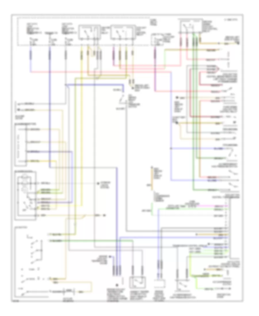
Manual A/C Wiring Diagram for Audi Cabriolet 1997
List of elements for Manual A/C Wiring Diagram for Audi Cabriolet 1997:
- (behind left side of dash) g202
- (in battery box) g100
- (near compressor)
- (not used)
- 1995 vftc c
- A/c clutch control module (on front aux relay panel)
- A/c compressor clutch
- A/c compressor speed sensor
- A/c flap solenoid
- A/c refrig- erant low pressure switch
- A/c refrigerant
- A/c refrigerant high pressure switch
- A/c switch
- Ambient temper- ature switch (right rear of eng compt)
- Auxiliary relay panel
- Blower motor
- Blower resistors
- Blower switch
- C10
- C11
- Coolant fan
- Coolant fan control relay
- Coolant fan control series resistors (left front conrner of engine compt)
- Coolant fan control thermoswitch
- Data link connector
- Engine control module (right side of dash)
- Engine coolant temperature electronic thermo switch (top rear corner of engine)
- Engine coolant temperature gauge
- Fuse 15a
- Fuse 25a
- Fuse 30a
- Fuse 60a
- Fuse/ relay panel
- G202 (behind left side of dash)
- Heater fan
- High pressure switch
- Hot at all times
- Hot with load reduction relay energized (x)
- Ignition (15)
- Interior lights system
- Off
- Protection diode
- Relay
- Second speed coolant fan control relay
- Third speed coolant fan control relay
- Transmission control module
- Wire distributor
 Čeština
 Dansk
Dansk Deutsch
 Ελληνικά
 English
 English
 Español
 Suomi
Suomi Français
 Français
 עברית
עברית Hrvatski
 Magyar
 日本語
日本語 한국어
한국어 Nederlands
 Polski
 Português
 Português
 Română
 Русский
 Slovenčina
 Slovenščina
 Svenska
 Türkçe
 中文 (中国)
 Italiano