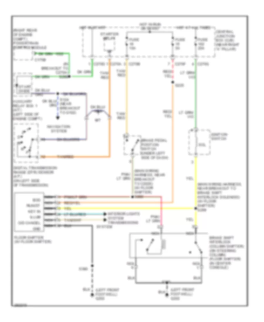
SHIFT INTERLOCK
Shift Interlock Wiring Diagram for Ford Pickup F150 2008
List of elements for Shift Interlock Wiring Diagram for Ford Pickup F150 2008:
- (in breakout to c270a) s298
- (left front footwell) g202
- (main wiring harness, near breakout to brake shift interlock solenoid) (w/ floor shifter) s299
- (main wiring harness, near breakout to c2026) (w/ floor shifter) s282
- (right rear of engine compt) powertrain control module
- Auxiliary relay box 1 (a/t) (left side of engine compt)
- Boo
- Brake pedal position switch (under left side of dash)
- Brake shift interlock (column shifter) (on steering column) (floor shifter) (in center console)
- C175b
- C270a
- C270b
- C270d
- C270f
- C270g
- Central junction box (cjb) (near right "a" pillar)
- Digital transmission range (dtr) sensor (a/t) (on left side of transmission)
- Floor shifter (w/ floor shifter)
- Fuse 10a
- Fuse 20a
- Fuse 5a
- Gnd
- Hot at all times
- Hot in run or start
- Hot in start
- Ignition switch
- Illum
- Interior lights system transmissions
- Key in
- M/t
- Navigation system
- Nca
- O/d cancel
- Run/st
- S205
- S225
- S380
- Sol
- Start diode
- Starter relay
- System
- Tan/ red
- Tan/red
 Čeština
 Dansk
Dansk Deutsch
 Ελληνικά
 English
 English
 Español
 Suomi
Suomi Français
 Français
 עברית
עברית Hrvatski
 Magyar
 日本語
日本語 한국어
한국어 Nederlands
 Polski
 Português
 Português
 Română
 Русский
 Slovenčina
 Slovenščina
 Svenska
 Türkçe
 中文 (中国)
 Italiano