SHIFT INTERLOCK
Shift Interlock Wiring Diagram for Pontiac Grand Prix GTP 2005
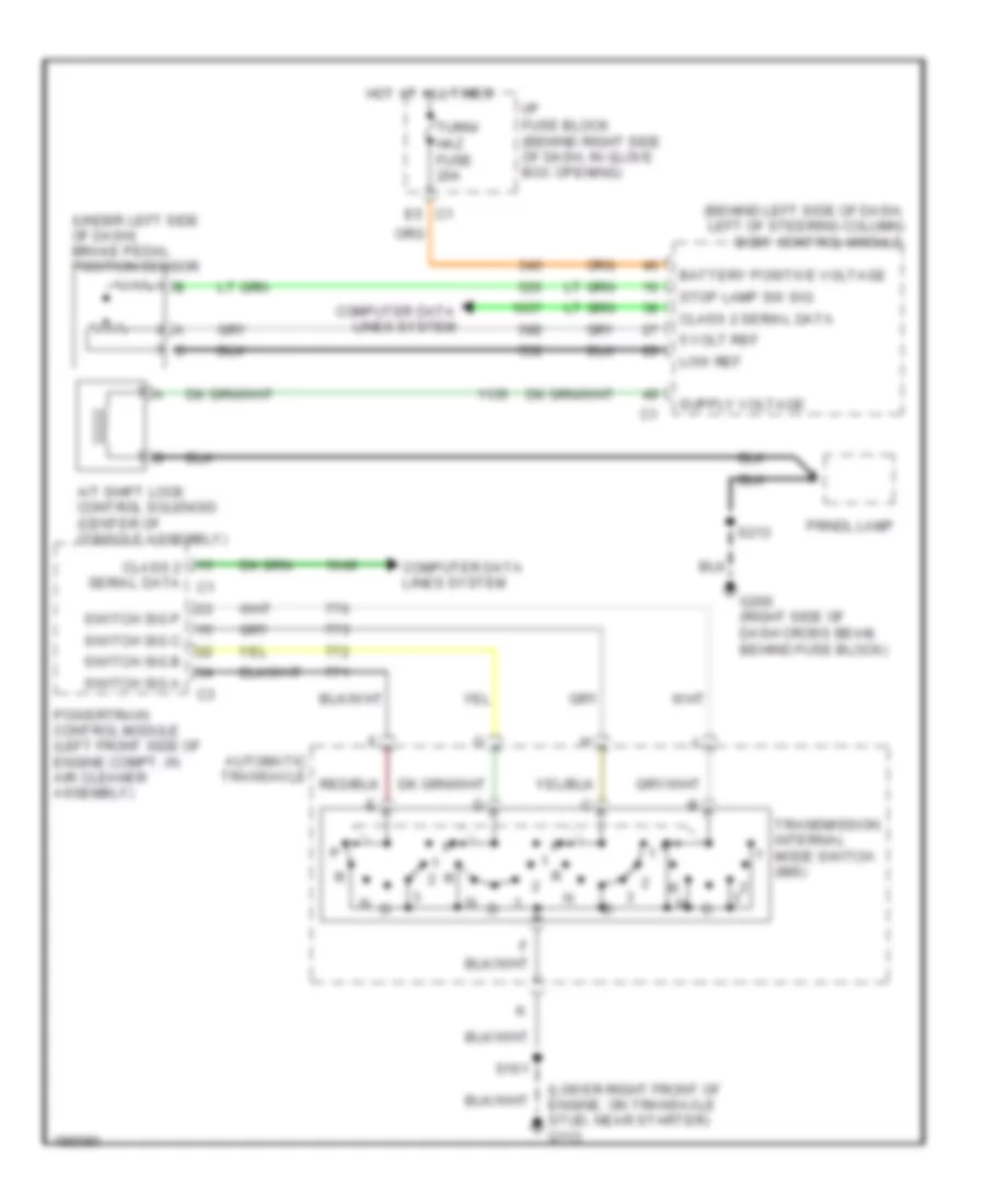
List of elements for Shift Interlock Wiring Diagram for Pontiac Grand Prix GTP 2005:
- (behind left side of dash, left of steering column) body control module
- (lower right front of engine, on transaxle stud, near starter) g113
- (under left side of dash) brake pedal position sensor
- 5 volt ref
- A/t shift lock control solenoid (center of console assembly)
- Automatic transaxle
- Battery positive voltage
- Class 2 serial data
- Class 2 serial data c1
- Computer data lines system
- E5 c1
- G200 (right side of dash cross beam, behind fuse block)
- Hot at all times
- I/p fuse block (behind right side of dash, in glove box opening)
- Low ref
- Powertrain control module (left front side of engine compt, in air cleaner assembly)
- Prndl lamp
- S101
- S213
- Stop lamp sw sig
- Switch sig a
- Switch sig b
- Switch sig c
- Switch sig p
- Transmission internal mode switch (ims)
- Turn/ haz fuse 20a
 Čeština
 Dansk
Dansk Deutsch
 Ελληνικά
 English
 English
 Español
 Suomi
Suomi Français
 Français
 עברית
עברית Hrvatski
 Magyar
 日本語
日本語 한국어
한국어 Nederlands
 Polski
 Português
 Português
 Română
 Русский
 Slovenčina
 Slovenščina
 Svenska
 Türkçe
 中文 (中国)
 Italiano