
 Čeština
 Dansk
Dansk Deutsch
 Ελληνικά
 English
 English
 Español
 Suomi
Suomi Français
 Français
 עברית
עברית Hrvatski
 Magyar
 Italiano
 한국어
한국어 Nederlands
 Polski
 Português
 Português
 Română
 Русский
 Slovenčina
 Slovenščina
 Svenska
 Türkçe
 中文 (中国)

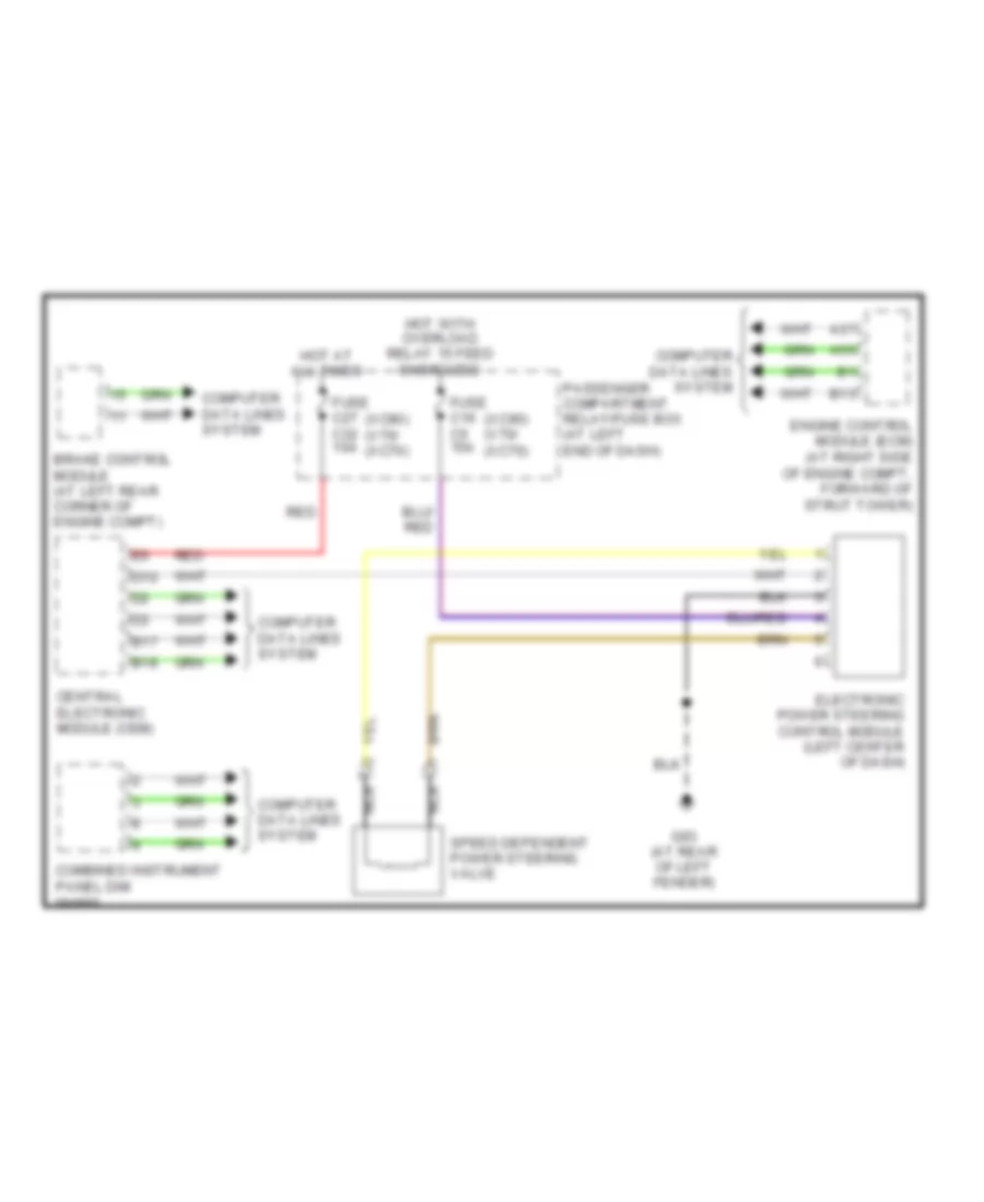
ELECTRONIC POWER STEERING
Electronic Power Steering Wiring Diagram for Volvo V70 R 2004
List of elements for Electronic Power Steering Wiring Diagram for Volvo V70 R 2004:

ANTI-LOCK BRAKESCOOLING FANAIR CONDITIONINGANTI-THEFTBODY CONTROL MODULESELECTRONIC POWER STEERINGCOMPUTER DATA LINESCRUISE CONTROLDEFOGGERSELECTRONIC SUSPENSIONEXTERIOR LIGHTSENGINE PERFORMANCEHORNGROUND DISTRIBUTIONHEADLIGHTSMEMORY SYSTEMSNAVIGATIONINSTRUMENT CLUSTERPOWER DOOR LOCKSINTERIOR LIGHTSPOWER SEATSPOWER MIRRORSPOWER DISTRIBUTIONPOWER TOP/SUNROOFPOWER WINDOWSTRANSMISSIONRADIOSUPPLEMENTAL RESTRAINTSSHIFT INTERLOCKSTARTING/CHARGINGWARNING SYSTEMSWIPER/WASHER