ENGINE PERFORMANCE
3.0L
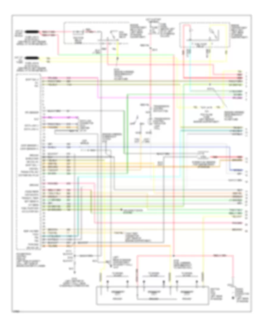
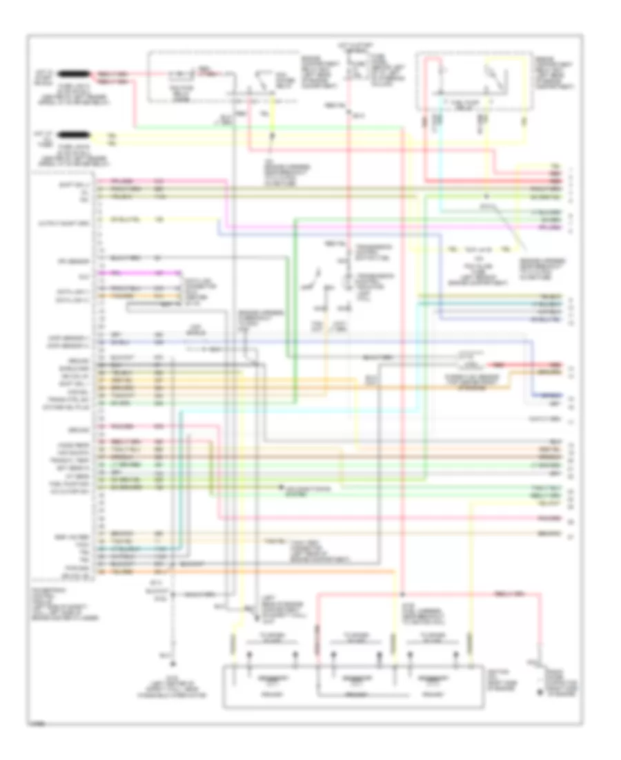
3.0L, Engine Performance Wiring Diagrams (1 of 4) for Ford Aerostar 1997
 https://portal-diagnostov.com/license.html
Automotive Electricians Portal FZCO
Automotive Electricians Portal FZCO
https://portal-diagnostov.com/license.html
https://portal-diagnostov.com/license.html
Automotive Electricians Portal FZCO
Automotive Electricians Portal FZCO
List of elements for 3.0L, Engine Performance Wiring Diagrams (1 of 4) for Ford Aerostar 1997:
- (ckp) sensor (+)
- (ckp) sensor (-)
- (engine harness, in breakout to pcm) s107
- (engine harness, near breakout to pcm inline fuse)
- (ho2s) rear
- (left rear of engine compartment, on safety wall)
- (pf) sensor
- 10a
- A/c cutoff sw
- Air conditioning system
- Ccs sol
- Ckp shield
- Data link (+)
- Data link (-)
- Data link connector (dlc) (center of i/p)
- Dlc
- Ect sens in
- Egr vac reg
- Engine compartment relay box (left rear of engine comartment)
- Engine compartment relay box (left rear of engine compartment)
- Fuel pump mon
- Fuel pump relay
- Fuse 15a
- Fuse panel (behind left of i/p, left of steering column)
- G103 (left center of safety wall, near windshield wiper motor)
- G107
- Ground
- Hot at all times
- Hot in start or run
- Iat sens
- Ign coil #1
- Ign coil #2
- Ignition coil (top left rear of engine)
- Maf sig rtn
- Mil
- Nca
- Octane adj plug
- Off
- Pcm inline fuse (left rear of engine compartment)
- Pcm power relay
- Pcm pwr relay diode
- Powertrain control module (left side of safety wall, left side of brake master cylinder)
- Primary
- Purge flow sensor (top center front of engine)
- Pwr gnd
- Radio noise capacitor (top left rear of engine)
- Red
- S101
- S109 (fuel harness, near breakout to ignition coil)
- S113
- S122
- S124 (engine harness, near breakout to pcm inline fuse)
- S213
- Secondary
- Shield gnd
- Shift sol 1
- Shift sol 2
- Tach
- To spark plugs
- Tr1
- Tr2
- Tr4
- Trans ctrl sw
- Trans fl temp
- Transmission control indicator lamp (tcil)
- Transmission control switch (tcs)
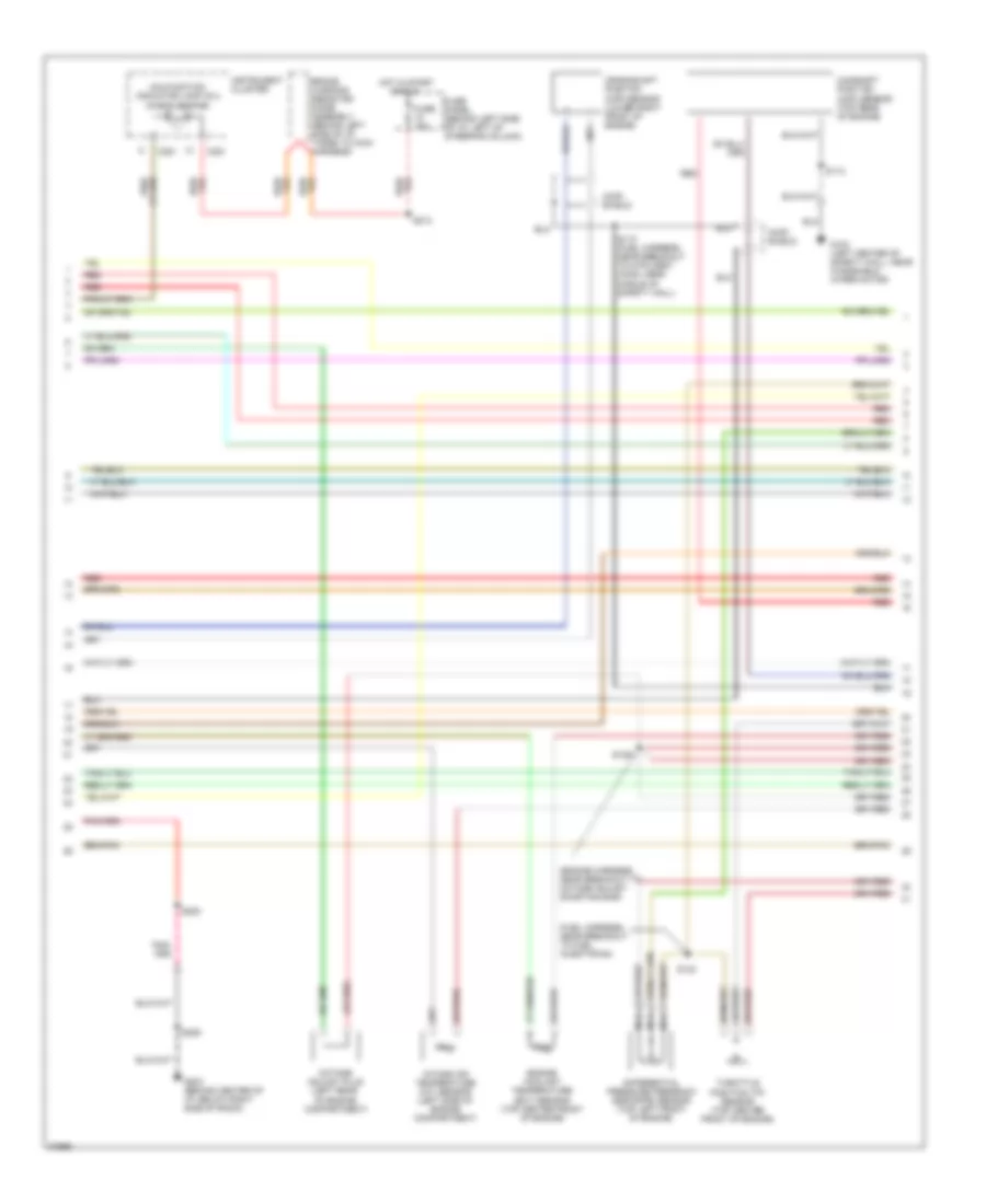
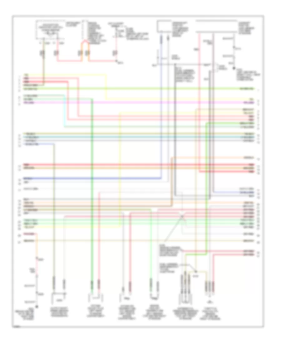
3.0L, Engine Performance Wiring Diagrams (2 of 4) for Ford Aerostar 1997
 https://portal-diagnostov.com/license.html
Automotive Electricians Portal FZCO
Automotive Electricians Portal FZCO
https://portal-diagnostov.com/license.html
https://portal-diagnostov.com/license.html
Automotive Electricians Portal FZCO
Automotive Electricians Portal FZCOList of elements for 3.0L, Engine Performance Wiring Diagrams (2 of 4) for Ford Aerostar 1997:
- (ckp) shield
- (cmp) shield
- (engine harness, near breakout to octane adjust shorting bar)
- (fuel harness, near breakout to fuel injector #4)
- Brake warning resistor/ diode assembly (behind left side of i/p, taped to main harness)
- C251
- Camshaft position (cmp) sensor (top rear of engine)
- Crankshaft position (ckp) sensor (lower right front of engine)
- Differential pressure feedback egr (dpfe) sensor (top left front of engine)
- Engine coolant temperature (ect) sensor (top center front of engine)
- Fuse 15a
- Fuse panel (behind left side of i/p, left of steering column)
- G103 (left center of safety wall, near windshield wiper motor)
- G203 (behind center of i/p, below right side of radio)
- Hot in start
- Instrument cluster
- Intake air temperature (iat) sensor (left side of engine compartment)
- Malfunction indicator lamp (mil) (check engine)
- Nca
- Octane adjust plug (left rear of engine compartment)
- Or run
- Red
- S110 (fuel harness, near breakout to 8-pin gray conn, near middle of safety wall)
- S113
- S123
- S125
- S200
- S209
- S213
- Throttle position (tp) sensor (top center front of engine)
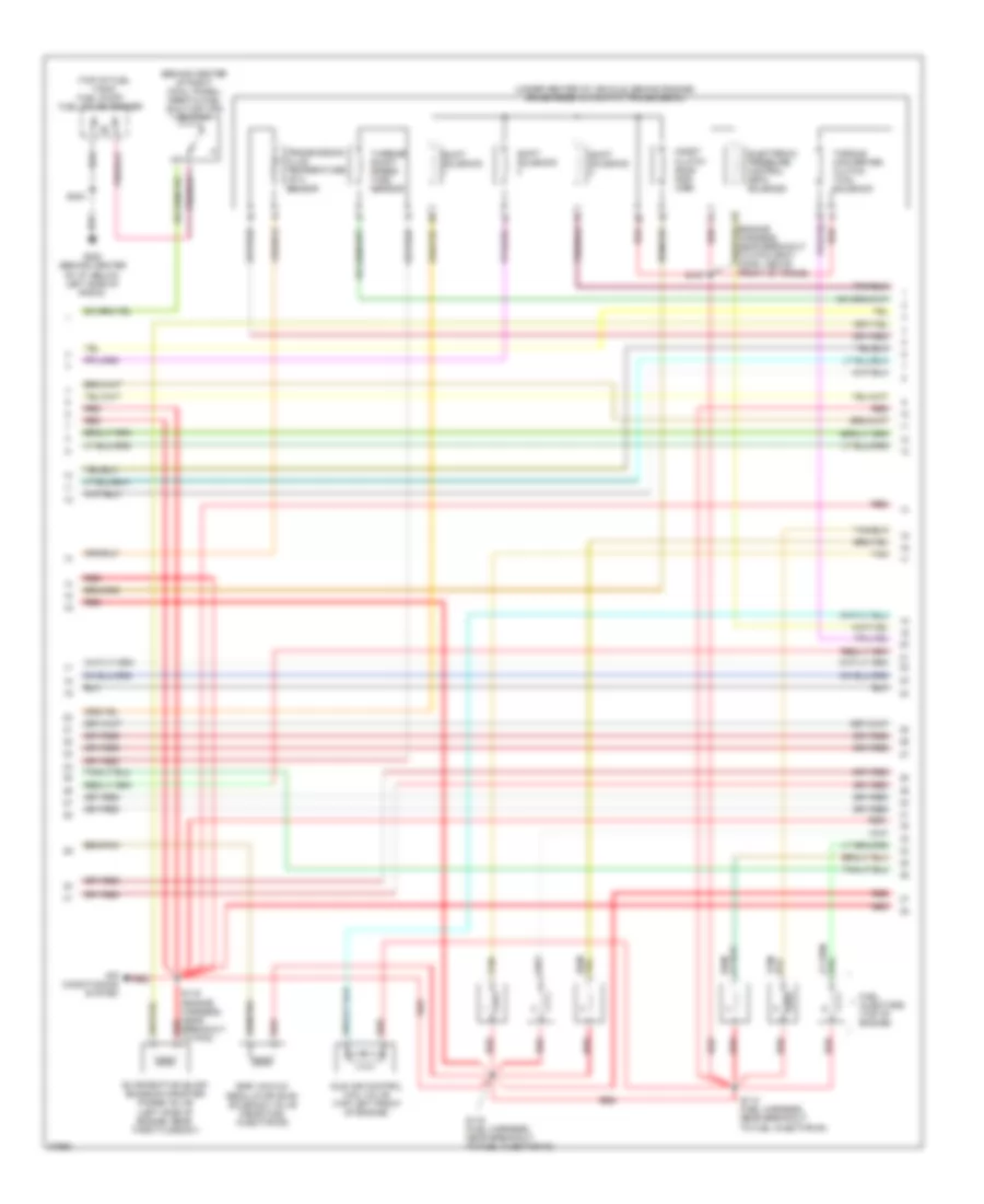
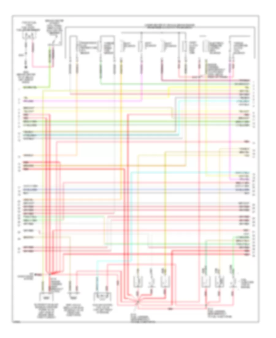
3.0L, Engine Performance Wiring Diagrams (3 of 4) for Ford Aerostar 1997
 https://portal-diagnostov.com/license.html
Automotive Electricians Portal FZCO
Automotive Electricians Portal FZCO
https://portal-diagnostov.com/license.html
https://portal-diagnostov.com/license.html
Automotive Electricians Portal FZCO
Automotive Electricians Portal FZCOList of elements for 3.0L, Engine Performance Wiring Diagrams (3 of 4) for Ford Aerostar 1997:
- (behind center of right cowl panel) inertia fuel shut-off (ifs) switch
- (top of fuel tank) fuel pump/ fuel gauge sender
- (under center of vehicle, behind engine) 4r44e/4r55e automatic transmission
- Air conditioning system
- Coast clutch sole- noid (css)
- Egr vacuum regulator (evr) solenoid valve (near fuel injector #3)
- Electronic pressure control (epc) solenoid
- Evaporative (evap) emission canister purge valve (left side of engine, near throttle body)
- Fuel injectors (top of engine)
- G200 (behind center of i/p, below left side of radio)
- Idle air control (iac) valve (top left front of engine)
- Red
- S115 (fuel harness, near breakout to fuel injector #4)
- S116 (engine harness, near breakout to pcm)
- S119 (fuel harness, near breakout to fuel injector #2)
- S127
- S204
- Shift solenoid
- Tan
- Torque converter clutch (tcc) solenoid
- Transmission fluid temperature (tft) sensor
- Turbine shaft speed (tss) sensor
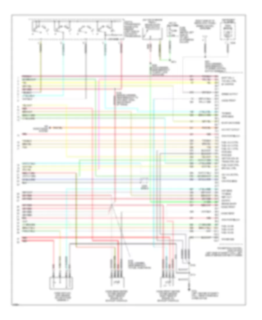
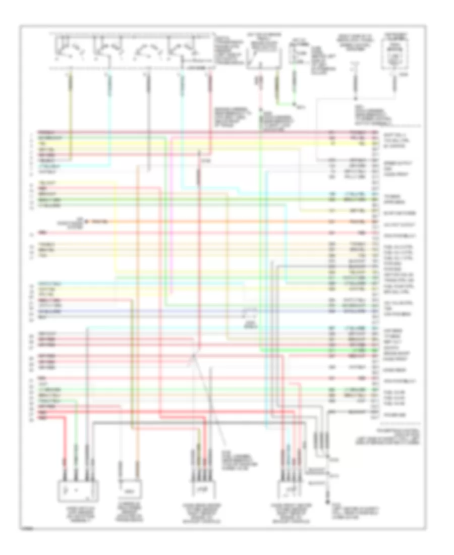
3.0L, Engine Performance Wiring Diagrams (4 of 4) for Ford Aerostar 1997
 https://portal-diagnostov.com/license.html
Automotive Electricians Portal FZCO
Automotive Electricians Portal FZCO
https://portal-diagnostov.com/license.html
https://portal-diagnostov.com/license.html
Automotive Electricians Portal FZCO
Automotive Electricians Portal FZCOList of elements for 3.0L, Engine Performance Wiring Diagrams (4 of 4) for Ford Aerostar 1997:
- (cmp) shield
- (h2os) front
- (ho2s) front
- (ho2s) front heated oxygen sensor (right rear of engine, on exhaust manifold)
- (ho2s) rear
- (ho2s) rear heated oxygen sensor (right rear of engine, on exhaust manifold)
- (on top of brake pedal)
- (pcm pwr relay)
- (right side of i/p, above cowl panel)
- 270 ohms
- A/c wot cutout
- Air conditioning system
- B+ (kapwr)
- Brake on/off
- Brake on/off (boo) switch
- C249
- Cam pos sens
- Digital transmission range (dtr) sensor (left side of automatic transmission)
- Dpfe sens
- Epc sol ctrl
- Evap can purge
- Fuel inj #2
- Fuel inj #4
- Fuel inj #6
- Fuel inj 1 ctrl
- Fuel inj 3 ctrl
- Fuel inj 5 ctrl
- Fuel pump ctrl
- Fuse 15a
- Fuse panel (behind left side of i/p/ left of steering column)
- G103 (left center of safety wall, near windshield wiper motor)
- Hot at all times
- Iac valve ctrl
- Ignition coil #3
- Instrument cluster
- Maf sens
- Mass air flow (maf) sensor (on air intake assembly)
- Nca
- Near breakout to shift lock actuator)
- Power gnd
- Powertrain control module (pcm) (left side of safety wall, left side of brake master cylinder)
- Psom module
- Pwr gnd
- Red
- Ref volt
- S113
- S122
- S128 (fuel harness, near breakout to fuel injector #4)
- S201 (main harness, near breakout to speed control switch assembly)
- S214
- Shift sol 3
- Sig rtn
- Speed control amplifier
- Speed output
- Tan
- Tcc sol ctrl
- Tp sens
- Tr sens
- Trans ctrl ind
- Tss
- Vss out- put
4.0L
4.0L, Engine Performance Wiring Diagrams (1 of 4) for Ford Aerostar 1997
 https://portal-diagnostov.com/license.html
Automotive Electricians Portal FZCO
Automotive Electricians Portal FZCO
https://portal-diagnostov.com/license.html
https://portal-diagnostov.com/license.html
Automotive Electricians Portal FZCO
Automotive Electricians Portal FZCOList of elements for 4.0L, Engine Performance Wiring Diagrams (1 of 4) for Ford Aerostar 1997:
- (ckp) sensor (+)
- (ckp) sensor (-)
- (engine harness, in breakout to pcm) s107
- (engine harness, near breakout to c112 pcm inline fuse)
- (ho2s) rear
- (left rear of engine compartment, on safety wall)
- (pf) sensor
- 10a
- A/c cutoff sw
- Air conditioning system
- Ccs sol
- Ckp shield
- Data link (+)
- Data link (-)
- Data link connector (dlc) (center of i/p)
- Dlc
- Ect sens in
- Egr vac reg
- Engine compartment relay box (left rear of engine comartment)
- Engine compartment relay box (left rear of engine compartment)
- Fuel pump mon
- Fuel pump relay
- Fuse 15a
- Fuse panel (behind left of i/p, left of steering column)
- G103 (left center of safety wall, near windshield wiper motor)
- G107
- Ground
- Hot at all times
- Hot in start or run
- Iat sens
- Ign coil #1
- Ign coil #2
- Ignition coil (right side of engine)
- Maf sig rtn
- Mil
- Nca
- Octane adj plug
- Off
- Output shaft spd
- Pcm inline fuse (left rear of engine compartment)
- Pcm power relay
- Pcm pwr relay diode
- Powertrain control module (left side of safety wall, left side of brake master cylinder)
- Primary
- Purge flow sensor (top center front of engine)
- Pwr gnd
- Radio noise capacitor (right side of engine)
- Red
- S101
- S109 (fuel harness, near breakout to ignition coil)
- S113
- S122
- S213
- Secondary
- Shield gnd
- Shift sol 1
- Shift sol 2
- Tach
- To spark plugs
- Tr1
- Tr2
- Tr4
- Trans ctrl sw
- Trans fl temp
- Transmission control indicator lamp (tcil)
- Transmission control switch (tcs)
4.0L, Engine Performance Wiring Diagrams (2 of 4) for Ford Aerostar 1997
 https://portal-diagnostov.com/license.html
Automotive Electricians Portal FZCO
Automotive Electricians Portal FZCO
https://portal-diagnostov.com/license.html
https://portal-diagnostov.com/license.html
Automotive Electricians Portal FZCO
Automotive Electricians Portal FZCOList of elements for 4.0L, Engine Performance Wiring Diagrams (2 of 4) for Ford Aerostar 1997:
- (ckp) shield
- (cmp) shield
- (fuel harness, near breakout to fuel injector #6)
- Brake warning resistor/ diode assembly (behind left side of i/p, taped to main harness)
- C251
- Camshaft position (cmp) sensor (top rear of engine)
- Crankshaft position (ckp) sensor (lower right front of engine)
- Differential pressure feedback egr (dpfe) sensor (top left front of engine)
- Engine coolant temperature (ect) sensor (top center front of engine)
- Fuse 15a
- Fuse panel (behind left side of i/p, left of steering column)
- G103 (left center of safety wall, near windshield wiper motor)
- G203 (behind center of i/p, below right side of radio)
- Hot in start
- Instrument cluster
- Intake air temperature (iat) sensor (left side of engine compartment)
- Malfunction indicator lamp (mil) (check engine)
- Nca
- Octane adjust plug (left rear of engine compartment)
- Or run
- Output shaft speed sensor (mounted on transmission)
- Red
- S110 (fuel harness, near breakout to 8-pin conn, near middle of safety wall)
- S113
- S123
- S125 (engine harness, near breakout to octane adjust shorting bar)
- S200
- S209
- S213
- Throttle position (tp) sensor (top center front of engine)
4.0L, Engine Performance Wiring Diagrams (3 of 4) for Ford Aerostar 1997
 https://portal-diagnostov.com/license.html
Automotive Electricians Portal FZCO
Automotive Electricians Portal FZCO
https://portal-diagnostov.com/license.html
https://portal-diagnostov.com/license.html
Automotive Electricians Portal FZCO
Automotive Electricians Portal FZCOList of elements for 4.0L, Engine Performance Wiring Diagrams (3 of 4) for Ford Aerostar 1997:
- (behind center of right cowl panel) inertia fuel shut-off (ifs) switch
- (top of fuel tank) fuel pump/ fuel gauge sender
- (under center of vehicle, behind engine) 4r44e/4r55e automatic transmission
- Air conditioning system
- Coast clutch sole- noid (css)
- Egr vacuum regulator (evr) solenoid valve (near fuel injector #3)
- Electronic pressure control (epc) solenoid
- Evaporative (evap) emission canister purge valve (left side of engine, near throttle body)
- Fuel injectors (top of engine)
- G200 (behind center of i/p, below left side of radio)
- Idle air control (iac) valve (top left front of engine)
- Red
- S115 (fuel harness, near breakout to fuel injector #6)
- S116 (engine harness, near breakout to pcm)
- S119 (fuel harness, near breakout to fuel injector #3)
- S127
- S204
- Shift solenoid
- Tan
- Torque converter clutch (tcc) solenoid
- Transmission fluid temperature (tft) sensor
- Turbine shaft speed (tss) sensor
4.0L, Engine Performance Wiring Diagrams (4 of 4) for Ford Aerostar 1997
 https://portal-diagnostov.com/license.html
Automotive Electricians Portal FZCO
Automotive Electricians Portal FZCO
https://portal-diagnostov.com/license.html
https://portal-diagnostov.com/license.html
Automotive Electricians Portal FZCO
Automotive Electricians Portal FZCOList of elements for 4.0L, Engine Performance Wiring Diagrams (4 of 4) for Ford Aerostar 1997:
- (cmp) shield
- (engine harness, near breakout to 8-pin gray conn, above front of trans)
- (h2os) front
- (ho2s) front
- (ho2s) front heated oxygen sensor (right rear of engine, on exhaust manifold)
- (ho2s) rear
- (ho2s) rear heated oxygen sensor (right rear of engine, on exhaust manifold)
- (on top of brake pedal)
- (pcm pwr relay)
- (right side of i/p, above cowl panel)
- 270 ohms
- A/c wot cutout
- Air conditioning system
- B+ (kapwr)
- Brake on/off
- Brake on/off (boo) switch
- C249
- Cam pos sens
- Digital transmission range (dtr) sensor (left side of automatic transmission)
- Dpfe sens
- Epc sol ctrl
- Evap can purge
- Fuel inj #2
- Fuel inj #4
- Fuel inj #6
- Fuel inj 1 ctrl
- Fuel inj 3 ctrl
- Fuel inj 5 ctrl
- Fuel pump ctrl
- Fuse 15a
- Fuse panel (behind left side of i/p/ left of steering column)
- G103 (left center of safety wall, near windshield wiper motor)
- Hot at all times
- Iac valve ctrl
- Ignition coil #3
- Instrument cluster
- Maf sens
- Mass air flow (maf) sensor (on air intake assembly)
- Nca
- Near breakout to shift lock actuator)
- Ods
- Overdrive drum speed sensor (mounted on transmission)
- Power gnd
- Powertrain control module (pcm) (left side of safety wall, left side of brake master cylinder)
- Psom module
- Pwr gnd
- Red
- Ref volt
- S113
- S122
- S126
- S128 (fuel harness, near breakout to evap canister purge valve)
- S201 (main harness, near breakout to speed control switch assembly)
- S214
- Shift sol 3
- Sig rtn
- Speed control amplifier
- Speed output
- Tan
- Tcc sol ctrl
- Tp sens
- Tr sens
- Trans ctrl ind
- Tss
- Vss out- put

 Čeština
 Dansk
Dansk Deutsch
 Ελληνικά
 English
 English
 Español
 Suomi
Suomi Français
 Français
 עברית
עברית Hrvatski
 Magyar
 Italiano
 日本語
日本語 Nederlands
 Polski
 Português
 Português
 Română
 Русский
 Slovenčina
 Slovenščina
 Svenska
 Türkçe
 中文 (中国)
