POWER DISTRIBUTION
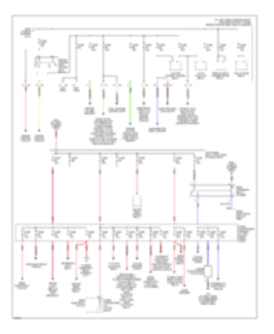
Power Distribution Wiring Diagram (1 of 3) for Volvo V70 R 2004
 https://portal-diagnostov.com/license.html
Automotive Electricians Portal FZCO
Automotive Electricians Portal FZCO
https://portal-diagnostov.com/license.html
https://portal-diagnostov.com/license.html
Automotive Electricians Portal FZCO
Automotive Electricians Portal FZCO
List of elements for Power Distribution Wiring Diagram (1 of 3) for Volvo V70 R 2004:
- (at left end of dash) passenger compartment fuse box
- (at left side of engine compt, forward of strut tower) engine compartment relay/fuse box
- Accessory (auxiliary light)
- Automatic transmission extended d2 feed relay
- Battery
- Brake control module (bcm)
- Brake light contact
- Capacitor
- Central electronic module
- Central electronic module & left/right cem indicator shunt
- Combustion preheater module (cpm)
- Cooling fan control module
- Data link connector, light switch module, climate control module & steering wheel module
- Extended d1 feed relay
- Fan control module
- From ignition switch (diagram 3 of 3)
- Fuel pump relay
- Fuse a2 60a
- Fuse a3 60a
- Fuse a4 60a
- Fuse a8 60a
- Fuse b1 25a
- Fuse b12 5a
- Fuse b13 25a
- Fuse b14 30a
- Fuse b16 15a
- Fuse b19 30a
- Fuse b2 20a
- Fuse b22 25a
- Fuse b9 15a
- Fuse c21 10a
- Fuse c22 20a
- Fuse c23 5a
- Fuse c24 10a
- Fuse c25 10a
- Fuse c26 30a
- Fuse c27 15a
- Fuse c28 10a
- Fuse c29 10a
- Fuse c30 7.5a
- Fuse c31 7.5a
- Fuse c32 10a
- Fuse c33 15a
- Fuse c34 15a
- Fuse c35 25a
- Fuse c36 25a
- Fuse c37 30a
- Fuse c38 5a
- G93 (rear of left front fender)
- Generator
- Horn relay
- Intermittent windshield wiper relay
- Jump start terminal
- Left front door control module
- Left front parking light
- Low/high speed windshield wiper relay
- Parking light/ position light tailight rem shunt
- Parking/position light relay
- Phone module
- Power window relay, rear door power window child lock, rear power window up relay, rear power window down relay, right rear power window
- Red
- Right front door control module
- Right front position/ parking light & right hand front lamp housing
- Right rear power window down relay,
- Siren control module
- Starter motor
- Starter motor relay
- Sun roof control module
- Suspension module relay
- To battery fuse box (diagram 2 of 3)
- To fuse b23 (diagram 2 of 3)
- To ignition switch, (diagram 3 of 3)
- To overload relays (diagram 3 of 3)
- Up relay &
- Upper electronic module
- Windshield washer motor relay
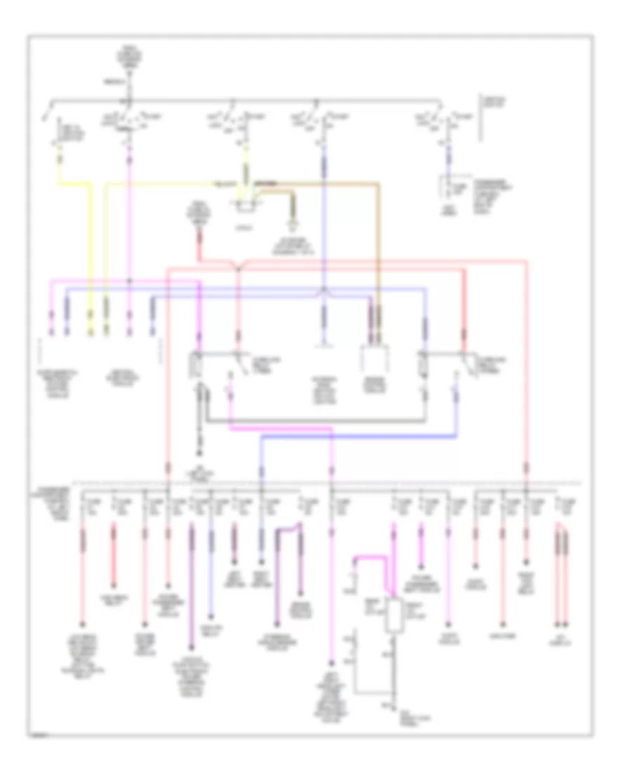
Power Distribution Wiring Diagram (2 of 3) for Volvo V70 R 2004
 https://portal-diagnostov.com/license.html
Automotive Electricians Portal FZCO
Automotive Electricians Portal FZCO
https://portal-diagnostov.com/license.html
https://portal-diagnostov.com/license.html
Automotive Electricians Portal FZCO
Automotive Electricians Portal FZCOList of elements for Power Distribution Wiring Diagram (2 of 3) for Volvo V70 R 2004:
- (at left side of engine compt, forward of strut tower) engine compartment relay/fuse box
- (not used)
- A red
- Accelerator pedal sensor
- Accessory electronic module & remote parking heater start control module
- Bass speaker
- Brake light relay & brake light rem shunt
- Cargo compartment 12v outlet
- Cargo compartment 12v outlet shunt
- Cargo compartment fuse box (at left side of cargo compt)
- Climate control system relay
- D18
- Differential electronic module
- Electrics box cooling fan
- Electronic throttle module & engine control module
- Engine control module
- Engine control module, fuel injectors & mass airflow sensor
- Engine manage- ment system main relay
- Evap valve, air preheating ptc resistor, turbocharger control valve, variable valve timing inlet solenoid, variable valve timing outlet solenoid, fuel cut off valve & fuel distributor
- From battery (diagram 1 of 3)
- From f fuse b2 (diagram 1 of 3)
- From fuse d5 (diagram 2 of 3)
- Fuel leakage control pump
- Fuel system relay
- Fuse a1 60a
- Fuse b10 10a
- Fuse b11 20a
- Fuse b15 15a
- Fuse b23 5a
- Fuse b3
- Fuse b4 20a
- Fuse b5 10a
- Fuse b6 15a
- Fuse b7 10a
- Fuse b8 10a
- Fuse d1 10a
- Fuse d10 10a
- Fuse d11 15a
- Fuse d12 15a
- Fuse d13 15a
- Fuse d15 20a
- Fuse d16 15a
- Fuse d17 7.5a
- Fuse d2 10a
- Fuse d3 15a
- Fuse d4 10a
- Fuse d5 5a
- Fuse d6 10a
- Fuse d7 15a
- Fuse d8 20a
- Fuse d9 15a
- Fuse e1 40a
- Fuse e2 40a
- Fuse e3 40a
- Fuse e4
- Fuse e5 40a
- Fuse e6
- Fuse e7 40a
- G73 (at right rear of passenger's compartment, near floor)
- Glow plug unit relay
- Heated oxygen sensors
- Heated rear window relay
- Intermittent rear window wiper on/off relay
- Main fuses (next to battery, in cargo comp)
- Rear accessory relay (15 feed)
- Rear doors deadlock relay, filler flap/rear doors locking relay, fuel filler flap unlocking relay, left hand rear unlocking relay & right hand rear unlocking relay
- Rear electrical module
- Rear electronic module
- Rear electronic module (rem)
- Rear window washer motor relay
- Rear window wiper relay
- Red
- Reversing light relay
- Road traffic information module & co changer
- Spark plug & ignition coil, egr valve, engine mounting solenoid valve & variable turbo geometry solenoid
- Tailgate unlocking relay
- To rear accessory relay (diagram) 2 of 3
- Towing bracket wiring
Power Distribution Wiring Diagram (3 of 3) for Volvo V70 R 2004
 https://portal-diagnostov.com/license.html
Automotive Electricians Portal FZCO
Automotive Electricians Portal FZCO
https://portal-diagnostov.com/license.html
https://portal-diagnostov.com/license.html
Automotive Electricians Portal FZCO
Automotive Electricians Portal FZCOList of elements for Power Distribution Wiring Diagram (3 of 3) for Volvo V70 R 2004:
- (not used)
- 15i
- Acc
- Amplifier
- Antenna ring/ ignition switch lighting
- Audio module
- Brake control module
- Central electronic module
- Cng/lpg relay
- Engine control module
- From fuse a3 (diagram 1 of 3)
- From fuse c25 (diagram 1 of 3)
- Front 12v outlet
- Front fog light relay
- Fuse c1 15a
- Fuse c12 15a
- Fuse c13 15a
- Fuse c14 5a
- Fuse c15 5a
- Fuse c16 20a
- Fuse c17 30a
- Fuse c18 15a
- Fuse c19 10a
- Fuse c2 20a
- Fuse c20
- Fuse c3 30a
- Fuse c4 30a
- Fuse c5 15a
- Fuse c6 5a
- Fuse c7 15a
- Fuse c8 15a
- Fuse c9 5a
- G10 (right kick panel)
- G6 (left kick panel)
- High beam relay
- Ignition switch
- J/c3lc
- Key in ignition switch
- Left seat heater
- Left/ right headlight wiper motor, left/right headlight adjustmemt motor
- Lock
- Low beam cem shunt, low beam/ bi-xenon relay, daytime running lights relay
- Nca
- Off
- On off
- Overload relay 15-feed
- Overload relay x feed
- Passenger compartment fuse box (at left end of dash)
- Power driver seat module
- Power passenger seat module
- Rear 12v outlet
- Red
- Right seat heater
- Rti display
- Start
- Starter motor relay (diagram 1 of 3)
- Steering angle sensor module
- Vaccum pump switch, electronic power steering control module

 Čeština
 Dansk
Dansk Deutsch
 Ελληνικά
 English
 English
 Español
 Suomi
Suomi Français
 Français
 עברית
עברית Hrvatski
 Magyar
 Italiano
 日本語
日本語 Nederlands
 Polski
 Português
 Português
 Română
 Русский
 Slovenčina
 Slovenščina
 Svenska
 Türkçe
 中文 (中国)
