ANTI-LOCK BRAKES
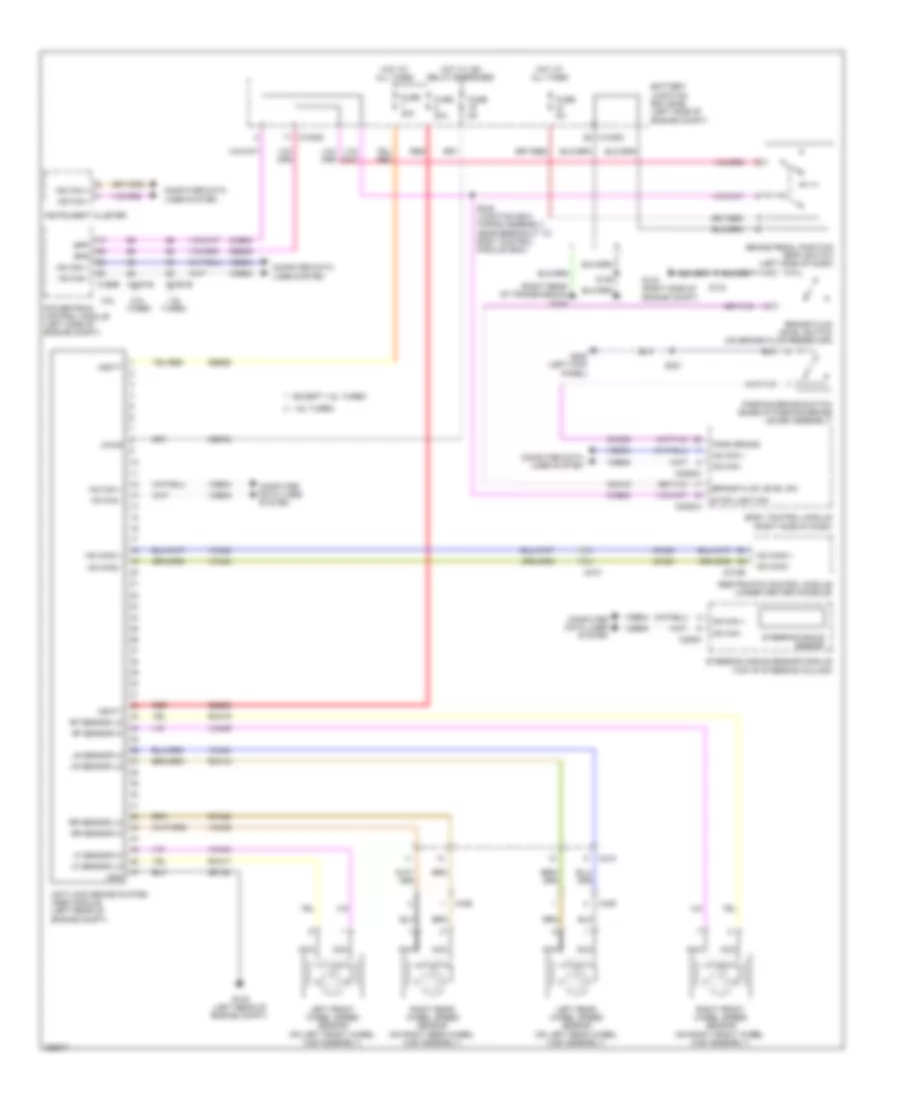
Anti-lock Brakes Wiring Diagram for Ford Escape S 2013
List of elements for Anti-lock Brakes Wiring Diagram for Ford Escape S 2013:
- (right rear of transmission) g104
- 1.6l turbo
- 2.0l turbo
- 2.5l
- Anti-lock brake system (abs) module (left rear of engine compt)
- Battery junction box (bjb) (left side of engine compt)
- Body control module (right side of dash)
- Bpp
- Bps
- Brake fluid level sw
- Brake fluid level switch (on brake fluid reservoir)
- Brake pedal position (bpp) switch (left side of dash)
- C1035c
- C1381b
- C1551b
- C175b
- C210
- C226a
- C2280a
- C2280c
- C310b
- C405
- C406
- Cbp03
- Ccb08
- Ces09
- Cmc19
- Cmc25
- Computer data lines system
- Except 1.6l turbo
- Fuse 30a
- Fuse 40a
- Fuse 5a
- G103 (right side of engine compt)
- G105 (left rear of engine compt)
- G205 (left kick panel)
- Gd122
- Gnd
- Hot at all times
- Hot w/ ign relay energized
- Hs can +
- Hs can -
- Hs can2 +
- Hs can2 -
- Instrument cluster
- Left front wheel speed sensor (on left front wheel hub assembly)
- Left rear wheel speed sensor (on left rear wheel hub assembly)
- Lf sensor hi
- Lf sensor lo
- Lr sensor hi
- Lr sensor lo
- Ms can +
- Ms can -
- Nca
- Park brake
- Parking brake switch (base of parking brake lever assembly)
- Powertrain control module (left side of engine compt)
- Rca17
- Rca18
- Rca19
- Rca20
- Red
- Restraints control module (under center console)
- Rf sensor hi
- Rf sensor lo
- Right front wheel speed sensor (on right front wheel hub assembly)
- Right rear wheel speed sensor (on right rear wheel hub assembly)
- Rr sensor hi
- Rr sensor lo
- S125
- S134
- S221
- S245 (junction box wiring assembly, near breakout to body control module (bcm)
- Sbb25
- Sbb26
- Steering angle sensor
- Steering angle sensor module (top of steering column)
- Stop light sw
- Vbatt
- Vca03
- Vca04
- Vca05
- Vca06
- Vca23
- Vca24
- Vdb04
- Vdb05
- Vpwr
 Čeština
 Dansk
Dansk Deutsch
 Ελληνικά
 English
 English
 Español
 Suomi
Suomi Français
 Français
 עברית
עברית Hrvatski
 Magyar
 Italiano
 日本語
日本語 한국어
한국어 Polski
 Português
 Português
 Română
 Русский
 Slovenčina
 Slovenščina
 Svenska
 Türkçe
 中文 (中国)
 Nederlands