SUPPLEMENTAL RESTRAINTS
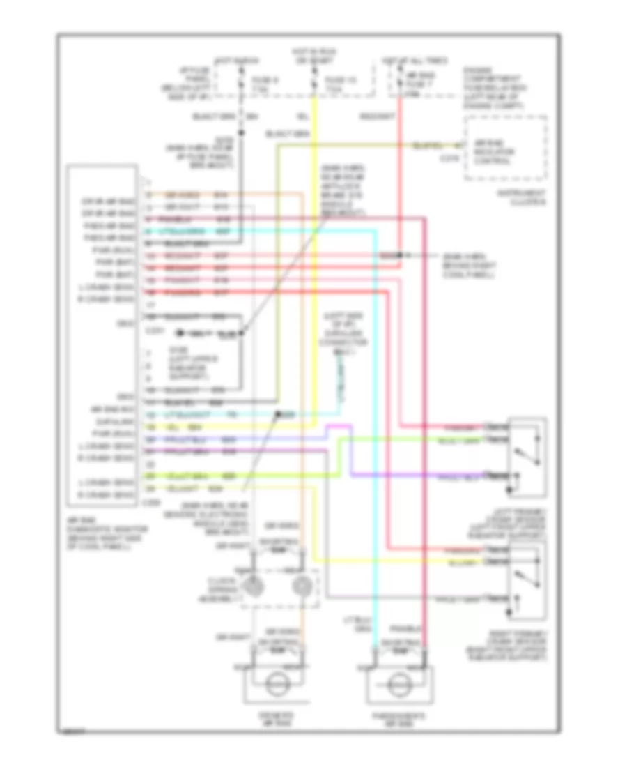
Supplemental Restraint Wiring Diagram, with Passenger Deactivation for Ford Ranger 1997
 https://portal-diagnostov.com/license.html
Automotive Electricians Portal FZCO
Automotive Electricians Portal FZCO
https://portal-diagnostov.com/license.html
https://portal-diagnostov.com/license.html
Automotive Electricians Portal FZCO
Automotive Electricians Portal FZCO
List of elements for Supplemental Restraint Wiring Diagram, with Passenger Deactivation for Ford Ranger 1997:
- (left side of i/p) data link connector (dlc)
- (main harn, behind right cowl panel)
- (main harn, near generic electronic module (gem) breakout)
- (main harn, near radio breakout)
- (main harn, near rear anti-lock brake sys module breakout)
- Air bag diagnostic monitor (behind right side of cowl panel)
- Air bag fuse 7 10a
- Air bag ind
- Air bag indicator control
- C216
- C250
- C251
- Clock- spring assembly
- Data link
- Driver's air bag
- Drvr air bag
- Engine compartment fuse/relay box (left rear of engine compt)
- Fuse 15 7.5a
- Fuse 6 7.5a
- G104 (top center of left fender apron)
- G108 (left upper radiator support)
- Gnd
- Hot at all times
- Hot in run
- Hot in run or start
- I/p fuse panel (below left side of i/p)
- Instrument cluster
- L crash sens
- Left primary crash sensor (left front upper radiator support)
- Nca
- Off
- Pass air bag
- Passenger's air bag
- Passive airbag deactivation (pad) module
- Pwr (bat)
- Pwr (run)
- R crash sens
- Right primary crash sensor (right front upper radiator support)
- S200
- S205
- S209
- S225
- S250 (main harn, near i/p fuse panel breakout)
- Shorting bar
Supplemental Restraint Wiring Diagram, without Passenger Deactivation for Ford Ranger 1997
List of elements for Supplemental Restraint Wiring Diagram, without Passenger Deactivation for Ford Ranger 1997:
- (left side of i/p) data link connector (dlc)
- (main harn, behind right cowl panel)
- (main harn, near generic electronic module (gem) breakout)
- (main harn, near rear anti-lock brake sys module breakout)
- Air bag diagnostic monitor (behind right side of cowl panel)
- Air bag fuse 7 10a
- Air bag ind
- Air bag indicator control
- C216
- C250
- C251
- Clock- spring assembly
- Data link
- Driver's air bag
- Drvr air bag
- Engine compartment fuse/relay box (left rear of engine compt)
- Fuse 15 7.5a
- Fuse 6 7.5a
- G108 (left upper radiator support)
- Gnd
- Hot at all times
- Hot in run
- Hot in run or start
- I/p fuse panel (below left side of i/p)
- Instrument cluster
- L crash sens
- Left primary crash sensor (left front upper radiator support)
- Nca
- Pass air bag
- Passenger's air bag
- Pwr (bat)
- Pwr (run)
- R crash sens
- Right primary crash sensor (right front upper radiator support)
- S200
- S205
- S225
- S250 (main harn, near i/p fuse panel breakout)
- Shorting bar

 Čeština
 Dansk
Dansk Deutsch
 Ελληνικά
 English
 English
 Español
 Suomi
Suomi Français
 Français
 עברית
עברית Hrvatski
 Magyar
 Italiano
 日本語
日本語 한국어
한국어 Nederlands
 Português
 Português
 Română
 Русский
 Slovenčina
 Slovenščina
 Svenska
 Türkçe
 中文 (中国)