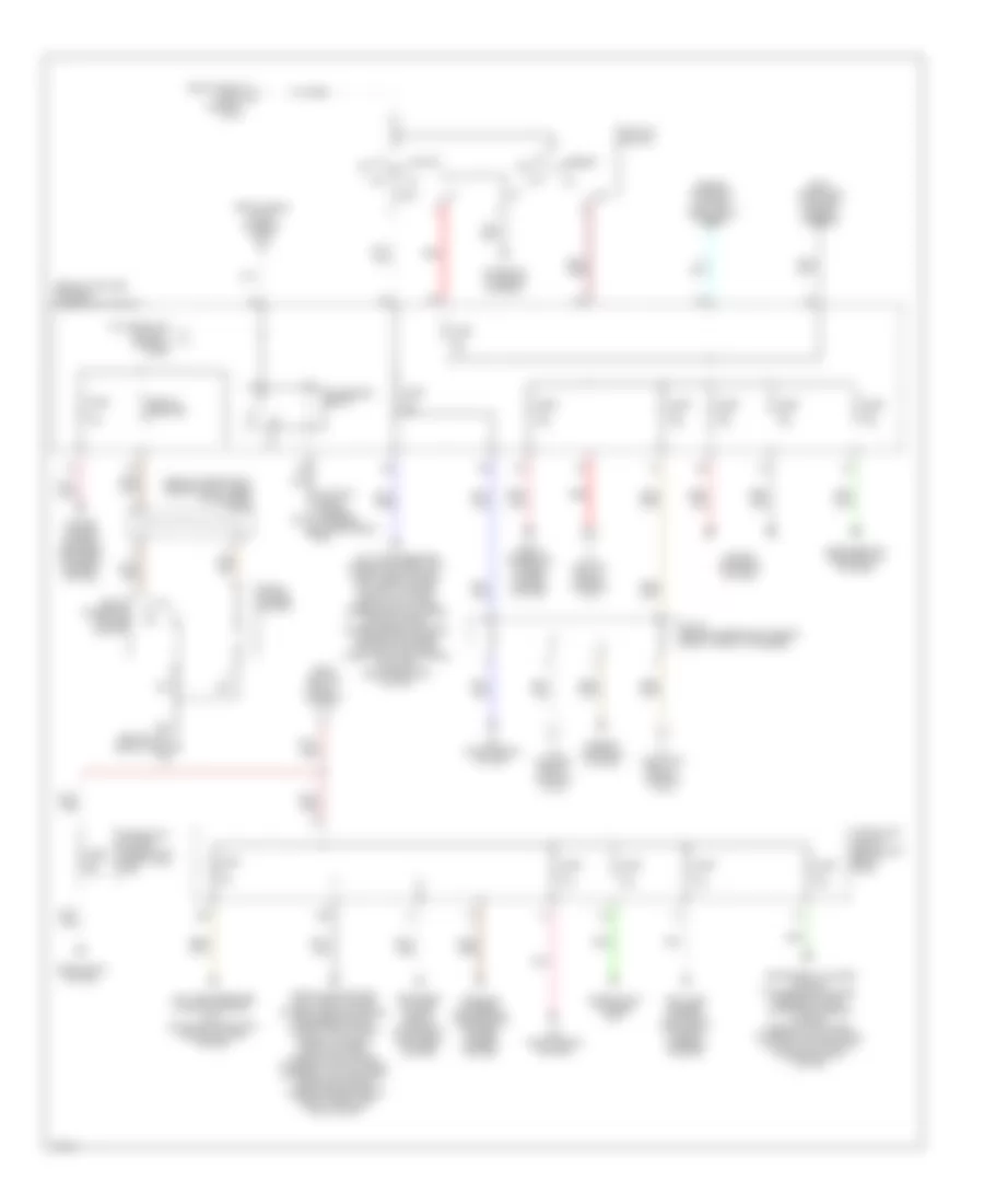
POWER DISTRIBUTION
Power Distribution Wiring Diagram (1 of 3) for Infiniti M45 2003

List of elements for Power Distribution Wiring Diagram (1 of 3) for Infiniti M45 2003:
- (at right side of engine compartment, in engine room box) fuse, fusible link & relay box
- 16r
- 20r
- 22r
- 23r
- 27r
- 28r
- 29r
- 33r
- 34r
- Air conditioner relay
- Air conditioning system
- Anti-lock brakes system
- Av & navi control unit, display, voice activated control module, sound system & navigation system, option connector-2 (for voice activated system), audio unit & cd auto changer
- Battery
- Blower relay
- Coil
- Contact
- Cruise control systyem
- E24 (at right side of engine compartment)
- Ecm relay
- Engine controls system
- Engine controls system, computer data lines system & transmissions system
- Engine controls system, transmissions system, shifty interlock system, door locks system, anti-theft system, power windows system, key switch & key lock solenoid (key switch)
- From fuse 13, 15a (diagram 2 of 3)
- From fuse 21, 10a (diagram 2 of 3)
- From ignition switch (diagram 2 of 3)
- Fuel pump relay
- Fuse 10a
- Fuse 15a
- Fuse 20a
- Fuse block (j/b) 2 (behind right kick panel)
- Fuse, fusible link & relay block (j/b) (at right side of engine compartment, in engine room box)
- Fuse, fusible link & relay box (at right side of engine compartment, in engine room box)
- Fusible link b 50a
- Fusible link c 50a
- Fusible link f 30a
- Fusible link g 50a
- Fusible link h 40a
- Fusible link k 50a
- Fusible link l 50a
- Headlamp relay 1
- Headlamp relay-2
- Headlights system
- Horn relay
- Ignition relay
- Nca
- Phone (handset)
- Pnk
- Red
- Seats system
- Security horn relay
- Sound system
- Starting/ charging system
- Tail lamp relay
- Throttle control motor relay
- To fuse block (j/b) no.1 (diagram 2 of 3)
- To fuse block (j/b) no.1 (diagram 3 of 3)
- To ignition switch (diagram 2 of 3)
- Transmissions system
- Wiper/ washer system
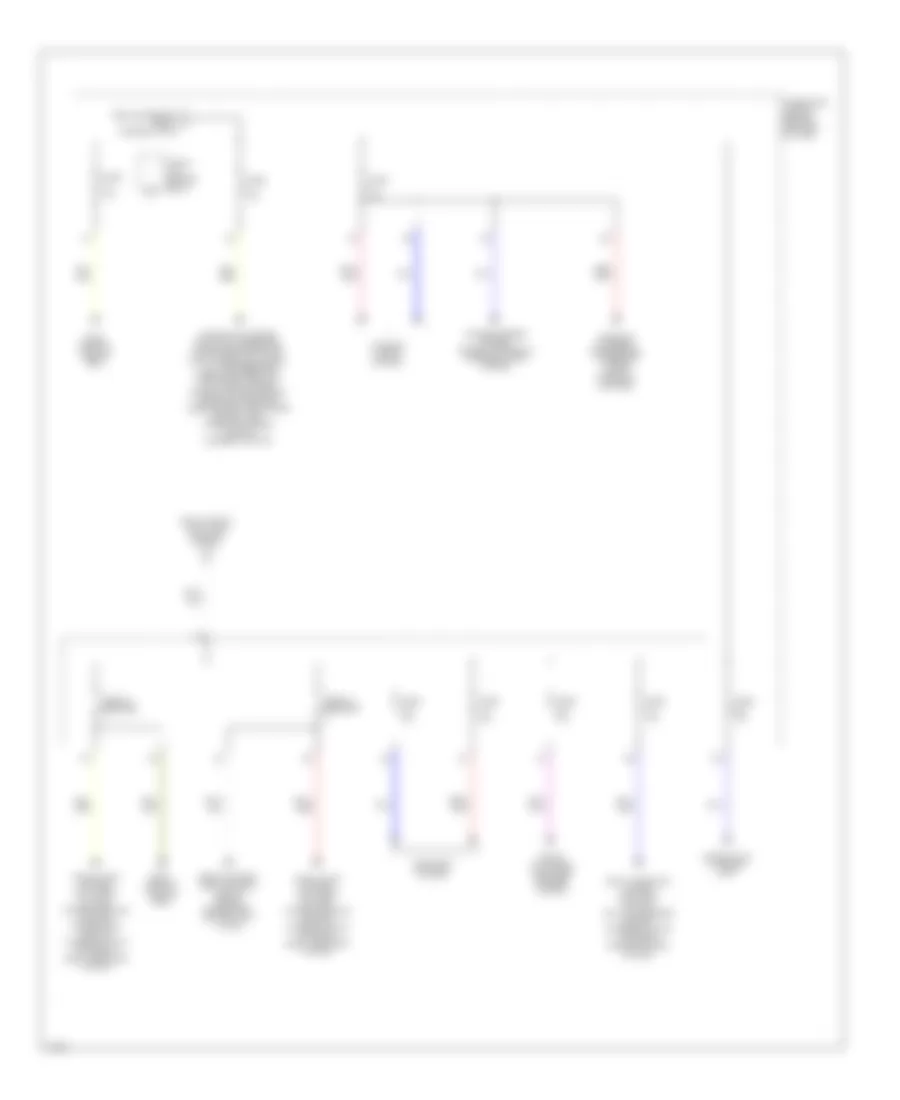
Power Distribution Wiring Diagram (2 of 3) for Infiniti M45 2003
List of elements for Power Distribution Wiring Diagram (2 of 3) for Infiniti M45 2003:
- (at right front corner of engine compartment) e42
- (behind left end of dash) fuse block (j/b) no.1
- (behind left side of dash) m24
- (behind upper right side of dash, taped to harness) j/c 15
- (diagram 1 of 3)
- 10a
- 10c
- 19b
- 20b
- Acc
- Accessory relay
- Air conditioning system
- Anti-lock brakes system & electronic power steering system
- Body computer system & memory systems
- Circuit breaker
- Combination flasher unit
- Defogger system, seats system & electronic mufflers system
- Door locks system, anti-theft system, power windows system, defogger system, power tops system, memory systems, seats system, headlights system, exterior lights system, interior lights system, warning systems, wiper/washer system & body computer module (bcm)
- Engine controls system
- Engine controls system, headlights system
- From fusible link c (diagram 1 of 3)
- From fusible link g c
- From ignition relay (diagram 1 of 3)
- Front cigarette lighter socket
- Front power socket
- Fuse 10a
- Fuse 15a
- Fuse block (in fuse, fusible link & relay box (j/b))
- Fuse block (j/b) no.1 (behind left end of dash)
- Headlights system
- Homelink universal transceiver, compass & power mirrors system
- Ign
- Ignition switch
- Instrument cluster system, transmission system, mirrors system, starting/charging system, headlights system, exterior lights system, navigation system & cruise control system
- J/c 19 (behind upper right side of dash, taped to harness)
- Low tire pressure warning control unit, door locks system, anti-theft system, memory systems, headlights system, interior lights system, sound system, power antenna system, combination meter, navigation system, voice activated control module & body computer system
- Low tire pressure warning control unit, navigation system & cruise control system
- Off
- Pnk
- Power mirrors system, defogger system & handset (option)
- Red
- Shift interlock system & cruise control system
- Start
- Starting/ charging system
- To blower relay (diagram 1 of 3)
- To fuel pump relay (diagram 1 of 3)
- To fuse block (j/b) no. 1 (diagram 3 0f 3)
- To ignition relay (diagram 1 of 3)
Power Distribution Wiring Diagram (3 of 3) for Infiniti M45 2003
List of elements for Power Distribution Wiring Diagram (3 of 3) for Infiniti M45 2003:
- (diagram 2 of 3)
- 10k
- 11b
- Body control module (bcm)
- Circuit breaker
- Coil
- Combination flasher unit
- Combination meter, data link connector, transmissions system, shift interlock system, low tire pressure warning control unit, anti-theft system, air conditioning system, headlights system, headlamp battery saver control unit, warning systems, clock & handset (option)
- Defogger system
- Door locks system, anti-theft system, power windows system, interior lights system & body computer system
- Door locks system, anti-theft system, power windows system, power tops system, interior lights system & body computer system
- From accessory relay k
- From fusible link h, 40a (diagram 1 of 3)
- Fuse 10a
- Fuse 15a
- Fuse 20a
- Fuse block (j/b) no.1 (behind left end of dash)
- Homelink universal transceiver, interior lights system & compass
- Interior lights system
- Power mirrors system, memory systems & interior lights system
- Seats system, body control module (bcm) & driver seat control unit (lcu02)
- Shift interlock system, stoplamp switch, anti-lock brakes system, exterior lights system & cruise control system
- Trunk lid opener relay
- Trunk, tailgate & fuel door release system