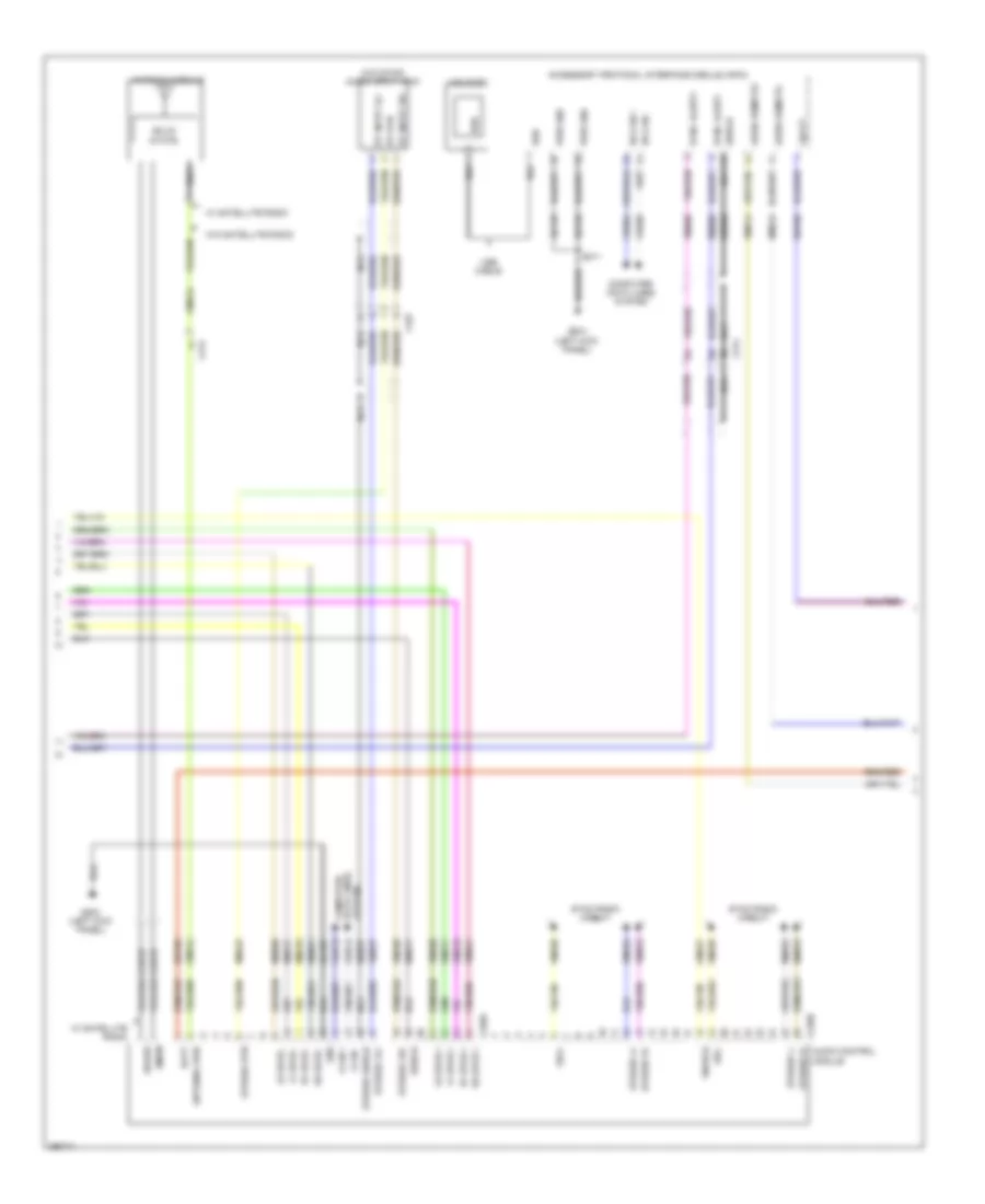
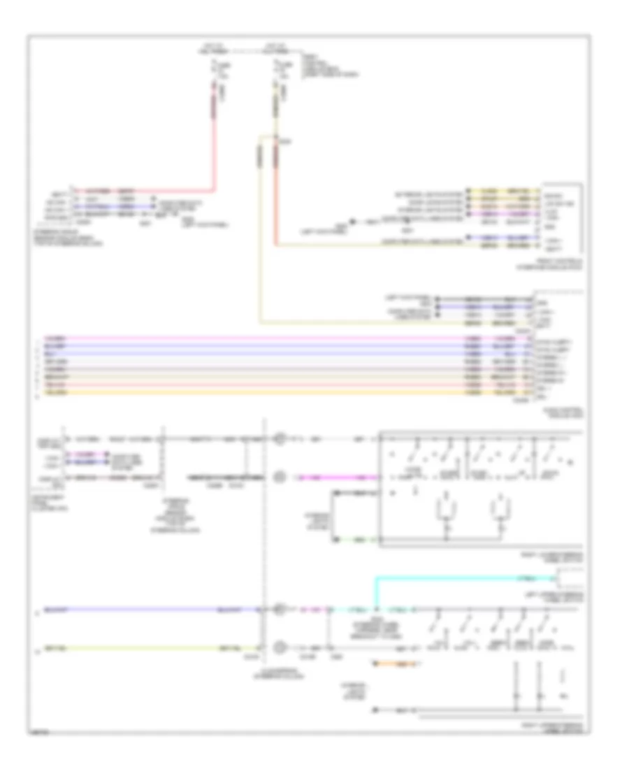
RADIO
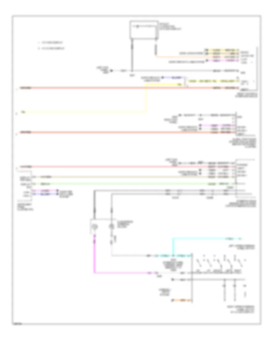
Radio Wiring Diagram, with Sony (1 of 3) for Ford Escape S 2013
 https://portal-diagnostov.com/license.html
Automotive Electricians Portal FZCO
Automotive Electricians Portal FZCO
https://portal-diagnostov.com/license.html
https://portal-diagnostov.com/license.html
Automotive Electricians Portal FZCO
Automotive Electricians Portal FZCO
List of elements for Radio Wiring Diagram, with Sony (1 of 3) for Ford Escape S 2013:
- Audio digital signal processing (dsp) module (left front of luggage area)
- C214
- C313
- C314
- C339
- C340
- C4326a
- C4326b
- C4326c
- Cme27
- Computer data lines system
- Enable
- Fuse 25a
- G401 (left "d" pillar)
- Gd180
- Gnd
- Hot at all times
- I can +
- I can -
- Instrument panel speaker
- Ip spkr +
- Ip spkr -
- Left front speaker
- Left front tweeter
- Left rear speaker
- Left rear tweeter
- Lf spkr +
- Lf spkr -
- Lf tweeter +
- Lf tweeter -
- Lr spkr +
- Lr spkr -
- Nca
- Rear junction box (behind right quarterpanel)
- Rf spkr +
- Rf spkr -
- Rf tweeter +
- Rf tweeter -
- Right front speaker
- Right front tweeter
- Right rear speaker
- Right rear tweeter
- Rme01
- Rme06
- Rme07
- Rme08
- Rme09
- Rme10
- Rme11
- Rme12
- Rme17
- Rme18
- Rme60
- Rme61
- Rme72
- Rme80
- Rr spkr +
- Rr spkr -
- S248 (main wiring assembly, in breakout to audio control module (acm))
- S418
- S419
- Sme23
- Subw 1+
- Subw 1-
- Subw 2+
- Subw 2-
- Subwoofer
- Sync alert+
- Sync alert-
- V batt
- Vdb13
- Vdb14
- Vme01
- Vme06
- Vme07
- Vme08
- Vme09
- Vme10
- Vme11
- Vme12
- Vme17
- Vme18
- Vme60
- Vme61
- Vme72
- Vme80
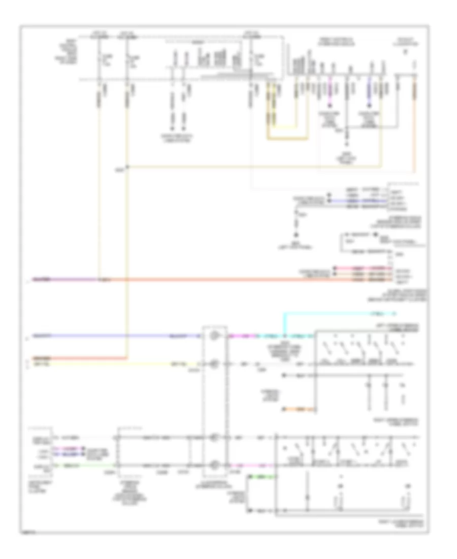
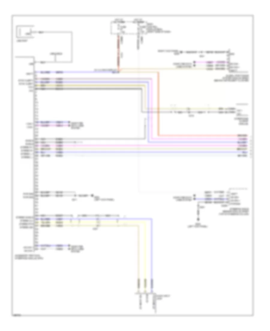
Radio Wiring Diagram, with Sony (2 of 3) for Ford Escape S 2013
List of elements for Radio Wiring Diagram, with Sony (2 of 3) for Ford Escape S 2013:
- (w/o sync) audio input jack
- Accessory protocol interface module (apim)
- Am/fm
- Antenna module
- Antenna pwr
- Audio control module
- Audio remote+
- Audio remote-
- Batt
- C214
- C240a
- C240b
- C327
- Cme27
- Cme44
- Coaxial cable
- Computer data lines system
- Data lines computer
- Dme17
- Dme37
- Dme80
- Enable
- G204 (left kick panel)
- Gd103
- Gd135
- Gnd
- Hs can +
- Hs can -
- I can +
- I can -
- Lf spkr +
- Lf spkr -
- Lr spkr +
- Lr spkr -
- Nca
- Pwr gnd
- Rf spkr +
- Rf spkr -
- Rme17
- Rme18
- Rme24
- Rme45
- Rme52
- Rme53
- Rme60
- Rme61
- Rme80
- Rr spkr +
- Rr spkr -
- S211
- Sbp06
- Sdars
- Sdl+
- Sdl-
- Shield
- Solid state
- St input 2l+
- St input 2r+
- St rtn
- Stereo 2l+
- Stereo 2r+
- Stereo l+
- Stereo l-
- Stereo r+
- Stereo r-
- Stereo rtn
- Stereo shield
- Sync alert+
- Sync alert-
- Sync radio circuit
- System
- Usb
- Usb cable
- Usb port
- Vbatt
- Vdb04
- Vdb05
- Vdb13
- Vdb14
- Vme14
- Vme17
- Vme18
- Vme37
- Vme38
- Vme52
- Vme53
- Vme58
- Vme59
- Vme60
- Vme61
- Vme80
- W/ satellite radio
- W/o satellite radio
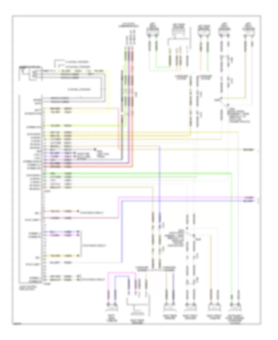
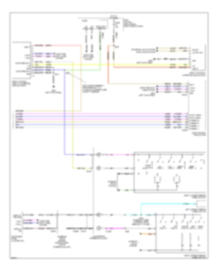
Radio Wiring Diagram, with Sony (3 of 3) for Ford Escape S 2013
List of elements for Radio Wiring Diagram, with Sony (3 of 3) for Ford Escape S 2013:
- Body control module (bcm) (right side of dash)
- C218a
- C218b
- C218c
- C226a
- C226b
- C2280c
- C2280e
- C2280f
- C260
- Ccd15
- Cd slot illumination
- Clockspring (steering column)
- Cls32
- Computer
- Computer data lines system
- Cpl87
- Ctrl sw ind
- Data lines system
- Display sig
- Display/ trip gnd
- Door lck
- Down
- Dr lck ctrl sw ind
- Front controls interface module
- Fuse 15a
- Fuse 7.5a
- G205 (left kick panel)
- G206 (right kick panel)
- Gd133
- Gd138
- Global positioning system module (gpsm) (behind instrument cluster)
- Gnd
- Hazard sig sw/
- Hot at all times
- Hs can +
- Hs can -
- I can +
- I can -
- Illum
- Instrument panel cluster
- Interior lights system
- Left upper steering wheel switch
- Micro
- Mode
- Ms can +
- Ms can -
- Nca
- Pwr gnd
- Right lower steering wheel switch
- Right upper steering wheel switch
- S214
- S221
- S235
- S241
- S242 (steering wheel harness, near breakout to c260)
- Sbp06
- Sbp07
- Seek+
- Seek-
- Sig sw/
- Start 1
- Start 2
- Steering angle sensor module (sasm) (top of steering column)
- Vbatt
- Vdb04
- Vdb05
- Vdb06
- Vdb07
- Vdb13
- Vdb14
- Vmn03
- Voice/ mute
- Vol+
- Vol-
- Warning
- Warning hazard
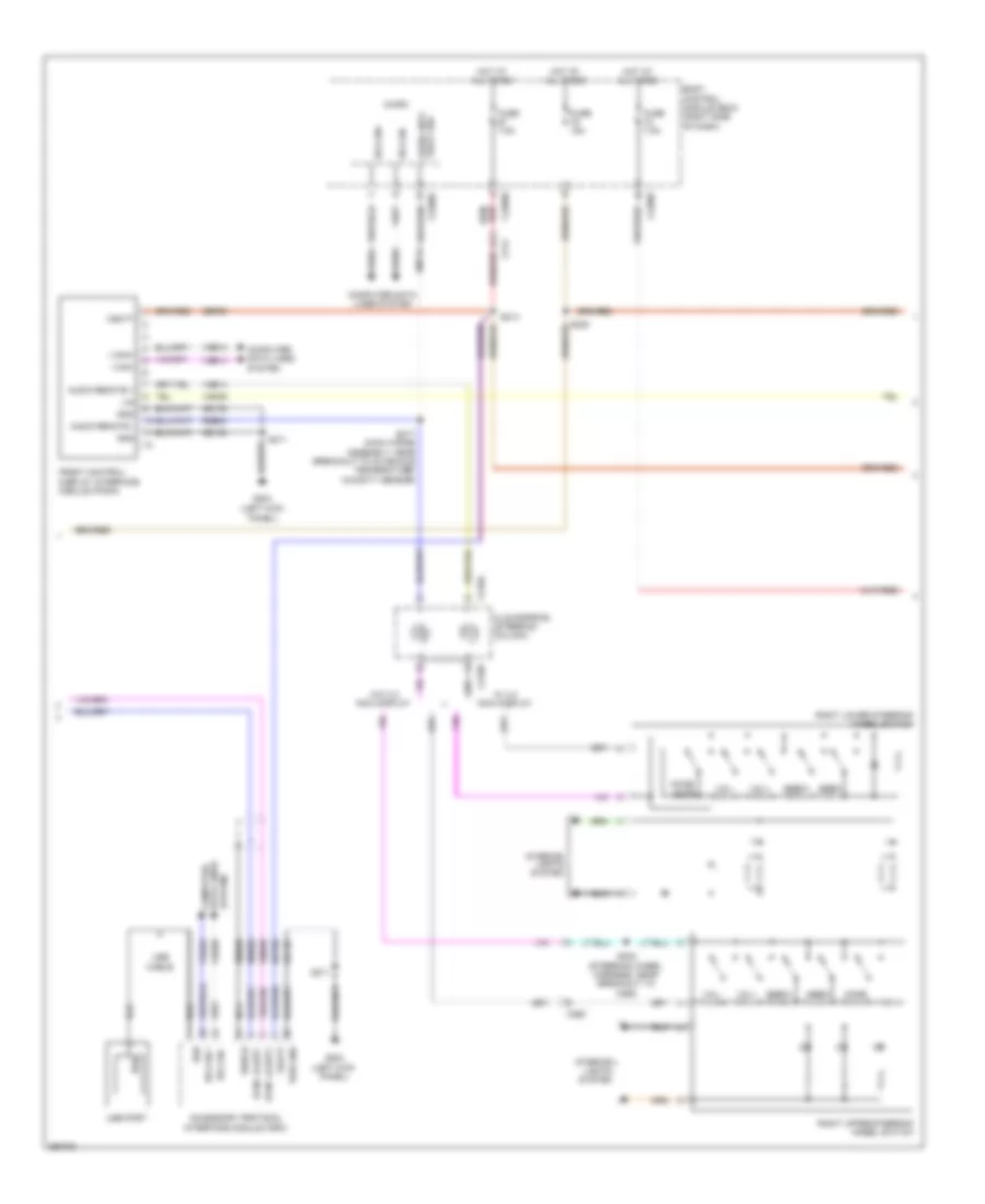
Radio Wiring Diagram, without Sony (1 of 3) for Ford Escape S 2013
List of elements for Radio Wiring Diagram, without Sony (1 of 3) for Ford Escape S 2013:
- (w/o sync) audio input jack
- 6 speaker system
- 9 speaker system
- Am/fm
- Antenna module
- Antenna pwr
- Audio control module (acm)
- Batt
- C214
- C240a
- C240b
- C313
- C314
- C327
- C339
- C340
- Cme44
- Cntr spkr +
- Cntr spkr -
- Coaxial cable
- Computer data lines system
- Dme37
- G204 (left kick panel)
- Gd103
- Gnd
- I can +
- I can -
- Instrument panel speaker (9 speaker system)
- Left front speaker
- Left front tweeter
- Left rear speaker
- Left rear tweeter
- Lf spkr +
- Lf spkr -
- Lr spkr +
- Lr spkr -
- Nca
- Rf spkr +
- Rf spkr -
- Right front speaker
- Right front tweeter
- Right rear speaker
- Right rear tweeter
- Rme06
- Rme07
- Rme09
- Rme10
- Rme12
- Rme45
- Rme52
- Rme53
- Rme80
- Rr spkr +
- Rr spkr -
- S207
- S208 (main wiring assembly, near breakout to data link connector (dlc))
- S239
- S240 (main wiring assembly, near breakout to headlamp control module (hcm))
- Sbp06
- Sdars
- Sdl +
- Sdl -
- St input 2l+
- St input 2r+
- St rtn
- State solid
- Stereo 2l+
- Stereo 2r+
- Stereo l+
- Stereo l-
- Stereo r+
- Stereo r-
- Stereo rtn
- Stereo shield
- Sync alert +
- Sync alert -
- Sync radio circuit
- Vdb13
- Vdb14
- Vme06
- Vme07
- Vme09
- Vme10
- Vme12
- Vme37
- Vme38
- Vme52
- Vme53
- Vme58
- Vme59
- Vme80
- W/ satellite radio
- W/o satellite radio
Radio Wiring Diagram, without Sony (2 of 3) for Ford Escape S 2013
List of elements for Radio Wiring Diagram, without Sony (2 of 3) for Ford Escape S 2013:
- Accessory protocol interface module (apim)
- Audio anti- theft sw
- Audio remote +
- Audio remote -
- Body control module (bcm) (right side of dash)
- C214
- C218a
- C218b
- C2280c
- C2280e
- C2280f
- C260
- Clockspring (steering column)
- Computer data lines system
- Dme80
- Front control/ display interface module (fcdim)
- Fuse 15a
- Fuse 7.5a
- G204 (left kick panel)
- Gd135
- Gd138
- Gnd
- Hot at all times
- Hs can +
- Hs can -
- Hs can+
- Hs can-
- I can+
- I can-
- Interior lights system
- Lin
- Micro
- Mode
- Nca
- Pwr gnd
- Right lower steering wheel switch
- Right upper steering wheel switch
- Rme24
- Rme80
- S211
- S214
- S217 (main wiring assembly, near breakout to in-vehicle temperature/ humidity sensor)
- S242 (steering wheel harness, near breakout to c260)
- Sbp06
- Seek+
- Seek-
- Shield
- Sync alert+
- Sync alert-
- Usb
- Usb cable
- Usb port
- Vbatt
- Vdb04
- Vdb05
- Vdb13
- Vdb14
- Vmc29
- Vme14
- Vme80
- Vmp19
- Voice/ mute
- Vol+
- Vol-
- W/ 4.2 inch display
- W/o 4.2 inch display
Radio Wiring Diagram, without Sony (3 of 3) for Ford Escape S 2013
List of elements for Radio Wiring Diagram, without Sony (3 of 3) for Ford Escape S 2013:
- (left kick panel) g205
- (or vdb13)
- C218b
- C218c
- C226a
- C226b
- C260
- Ccd15
- Cd slot illumination (w/ 8 inch display)
- Clockspring (steering column)
- Cls32
- Cmc29
- Computer data lines system
- Cpl87
- Display sig
- Display/ trip gnd
- Door locks system
- Down
- Front controls interface module
- G206 (right kick panel)
- Gd133
- Gd138
- Global positioning system module (gpsm) (behind instrument cluster)
- Gnd
- Hs can +
- Hs can -
- I can +
- I can + lin
- I can -
- I can-
- Illum
- Instrument panel cluster (ipc)
- Interior lights system
- Lck sw ind
- Left
- Left upper steering wheel switch
- Ms can +
- Ms can -
- Nca
- Pwr gnd
- Right
- Right upper steering wheel switch (w/ 4.2 inch display)
- Rmc27
- S221
- S241
- S242 (steering wheel harness, near breakout to c260)
- Sbp06
- Sbp07
- Sig sw
- Steering angle sensor module (sasm) (top of steering column)
- Vbatt
- Vdb04
- Vdb05
- Vdb06
- Vdb07
- Vdb14
- Vmc29
- Vmn03
- W/ 4.2 inch display
- W/ 8 inch display
SYNC Radio Wiring Diagram, with SYNC GEN 1 (1 of 2) for Ford Escape S 2013
List of elements for SYNC Radio Wiring Diagram, with SYNC GEN 1 (1 of 2) for Ford Escape S 2013:
- (right kick panel) g206
- (w/ 4.2 inch display) s214
- Accessory protocol interface module (apim)
- Audio input jack
- Body control module (bcm) (right side of dash)
- C214
- C215
- C226a
- C2280e
- C2280f
- C327
- Computer data lines system
- Dme37
- Dme52
- Dme80
- Dmm13
- Fuse 7.5a
- G204 (left kick panel)
- G205 (left kick panel)
- Gd135
- Gd138
- Global positioning system module (gpsm) (behind instrument cluster)
- Gnd
- Hot at all times
- Hs can +
- Hs can -
- I can +
- I can -
- Mic+
- Mic-
- Microphone (in roof module)
- Ms can +
- Ms can -
- Nca
- Nca mic + nca mic -
- Pwr gnd
- Rme45
- Rme52
- Rme53
- Rme80
- S211
- S221
- S241
- Sbp06
- Sbp07
- Shield
- St input 2l+
- St input 2r+
- St rtn
- Steering angle sensor module (sasm) (top of steering column)
- Stereo 2l+
- Stereo 2r+
- Stereo l +
- Stereo l -
- Stereo r +
- Stereo r -
- Stereo rtn
- Stereo shield
- Sync alert+
- Sync alert-
- Usb
- Usb cable
- Usb port
- Vbatt
- Vdb04
- Vdb05
- Vdb06
- Vdb07
- Vdb13
- Vdb14
- Vme37
- Vme38
- Vme52
- Vme53
- Vme80
- Vmm13
- Vmn03
SYNC Radio Wiring Diagram, with SYNC GEN 1 (2 of 2) for Ford Escape S 2013
List of elements for SYNC Radio Wiring Diagram, with SYNC GEN 1 (2 of 2) for Ford Escape S 2013:
- (main wiring assembly, near breakout to in-vehicle temperature/ humidity sensor)
- Audio anti- theft sw
- Audio control module (acm)
- Audio remote +
- Audio remote -
- Batt
- Body control module (bcm) (right side of dash)
- C218a
- C218b
- C218c
- C226a
- C226b
- C2280c
- C2280f
- C240a
- C240b
- C260
- Clockspring (steering column)
- Cls32
- Cmc29
- Computer data lines system
- Cpl87
- Display sig
- Display/ trip gnd
- Door locks system
- Down
- Exterior lights system
- Front control/ display interface module (fcdim)
- Front controls interface module (fcim)
- Fuse 15a
- G204 (left kick panel)
- G205 (left kick panel)
- Gd103
- Gd133
- Gd138
- Gnd
- Hot at all times
- Hs can+
- Hs can-
- I can +
- I can -
- I can+
- I can-
- Instrument panel cluster (ipc)
- Interior lights system
- Lck sw ind
- Left
- Left upper steering wheel switch
- Lin
- Micro
- Nca
- Right
- Right lower steering wheel switch
- Right upper steering wheel switch
- Rmc27
- Rme24
- Rme52
- Rme53
- Rme80
- S211
- S217
- S221
- S235
- S242 (steering wheel harness, near breakout to c260)
- Sbp06
- Seek +
- Seek -
- Sig sw
- Steering angle sensor module (sasm) (top of steering column)
- Stereo l +
- Stereo l -
- Stereo r +
- Stereo r -
- Sync alert+
- Sync alert-
- Vbatt
- Vdb04
- Vdb05
- Vdb13
- Vdb14
- Vmc29
- Vme14
- Vme52
- Vme53
- Vme80
- Vmp19
- Voice/ mute
- Vol +
- Vol -
SYNC Radio Wiring Diagram, with SYNC GEN 2 (1 of 2) for Ford Escape S 2013
List of elements for SYNC Radio Wiring Diagram, with SYNC GEN 2 (1 of 2) for Ford Escape S 2013:
- (behind instrument cluster) global positioning system module (gpsm)
- (right kick panel) g206
- 5v pwr
- Accessory protocol interface module (apim)
- Audio digital signal processing (dsp) module (left front of luggage area)
- Aux audio l+
- Aux audio l-
- Aux audio r+
- Aux audio r-
- Aux video+
- Aux video-
- Body control module (bcm) (right side of dash)
- C214
- C215
- C2280e
- C327
- C4326a
- Computer data lines system
- Dm19c
- Dme45
- Dme52
- Dme80
- Dmm13
- Fuse 7.5a
- G204 (left kick panel)
- Gd135
- Gd138
- Gnd
- Hot at all times
- Hs can +
- Hs can -
- I can +
- I can -
- Media gnd
- Media hub
- Mic +
- Mic -
- Microphone (in roof module)
- Ms can +
- Ms can -
- Navigation system
- Nca
- Nca mic + nca mic -
- Pwr gnd
- Remote +
- Remote -
- Rme19
- Rme24
- Rme45
- Rme46
- Rme52
- Rme53
- Rme67
- Rme80
- Rmp31
- S211
- S214
- S241
- Sbp06
- Sdl +
- Sdl -
- Shield
- Stereo l +
- Stereo l -
- Stereo r +
- Stereo r -
- Sync alert+
- Sync alert-
- Usb
- Usb cable
- Vbatt
- Vdb04
- Vdb05
- Vdb06
- Vdb07
- Vdb13
- Vdb14
- Video +
- Video -
- Vme14
- Vme19
- Vme45
- Vme46
- Vme52
- Vme53
- Vme58
- Vme59
- Vme67
- Vme80
- Vmm13
- Vmn03
- Vmp31
- W/ sony radio
- W/o sony radio
SYNC Radio Wiring Diagram, with SYNC GEN 2 (2 of 2) for Ford Escape S 2013
List of elements for SYNC Radio Wiring Diagram, with SYNC GEN 2 (2 of 2) for Ford Escape S 2013:
- (left kick panel) g204
- Audio control module (acm)
- Batt
- Body control module (bcm) (right side of dash)
- C218a
- C218b
- C218c
- C226a
- C226b
- C2280f
- C240a
- C240b
- C260
- Ccd15
- Clockspring (steering column)
- Cls32
- Cmc29
- Computer data lines system
- Cpl87
- Display sig
- Display/ trip gnd
- Door locks system
- Down
- Exterior lights system
- Front controls interface module (fcim)
- Fuse 15a
- Fuse 7.5a
- G205 (left kick panel)
- Gd103
- Gd133
- Gd138
- Gnd
- Hot at all times
- Hs can +
- Hs can -
- I can +
- I can -
- Iilum
- Instrument panel cluster (ipc)
- Interior lights system
- Lck sw ind
- Left upper steering wheel switch
- Mode
- Nca
- Pwr gnd
- Right lower steering wheel switch
- Right upper steering wheel switch
- Rmc27
- Rme52
- Rme53
- Rme80
- S221
- S235
- S242 (steering wheel harness, near breakout to c260)
- Sbp06
- Sbp07
- Sdl +
- Sdl -
- Seek+
- Seek-
- Sig sw
- Star1
- Star2
- Steering angle sensor module (sasm) (top of steering column)
- Stereo l +
- Stereo l -
- Stereo r +
- Stereo r -
- Sync alert+
- Sync alert-
- Vbatt
- Vdb04
- Vdb05
- Vdb13
- Vdb14
- Vme52
- Vme53
- Vme58
- Vme59
- Vme80
- Voice/ mute
- Vol+
- Vol-

 Čeština
 Dansk
Dansk Deutsch
 Ελληνικά
 English
 English
 Español
 Suomi
Suomi Français
 Français
 עברית
עברית Hrvatski
 Magyar
 Italiano
 日本語
日本語 한국어
한국어 Nederlands
 Polski
 Português
 Română
 Русский
 Slovenčina
 Slovenščina
 Svenska
 Türkçe
 中文 (中国)