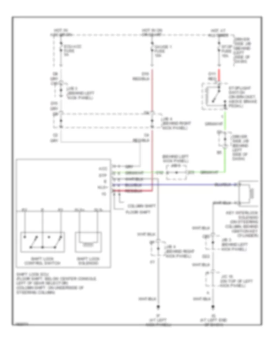
SHIFT INTERLOCK
Shift Interlock Wiring Diagram for Toyota Avalon XL 2004
List of elements for Shift Interlock Wiring Diagram for Toyota Avalon XL 2004:
- (behind left kick panel) j/b 3
- Acc
- C12
- C15
- C22
- Column shift
- D11 red
- D15
- D22
- Driver side j/b (behind left side of dash)
- Ecu-acc fuse 5a
- Floor shift
- Gauge 1 fuse 10a
- Hot at all times
- Hot in acc or on
- Hot in on or start
- If (at left kick panel)
- Ig (at left end of dash)
- J/b 3 (behind left kick panel)
- J/b 4 (behind right kick panel)
- J/c 16 (on top of left kick panel)
- Key interlock solenoid (on steering column, behind ignition key cylinder)
- Kls+
- Shift lock control switch
- Shift lock ecu (floor shift: below center console, left of gear selector) (column shift: on underside of steering column)
- Shift lock solenoid
- Sls+
- Sls-
- Stop fuse 15a
- Stoplight switch (on bracket, above brake pedal)
- Stp
 Čeština
 Dansk
Dansk Deutsch
 Ελληνικά
 English
 English
 Español
 Suomi
Suomi Français
 Français
 עברית
עברית Hrvatski
 Magyar
 Italiano
 日本語
日本語 한국어
한국어 Nederlands
 Polski
 Português
 Română
 Русский
 Slovenčina
 Slovenščina
 Svenska
 Türkçe
 中文 (中国)
 Português