
 Čeština
 Dansk
Dansk Deutsch
 Ελληνικά
 English
 English
 Español
 Suomi
Suomi Français
 Français
 עברית
עברית Hrvatski
 Magyar
 Italiano
 日本語
日本語 한국어
한국어 Nederlands
 Polski
 Português
 Português
 Русский
 Slovenčina
 Slovenščina
 Svenska
 Türkçe
 中文 (中国)

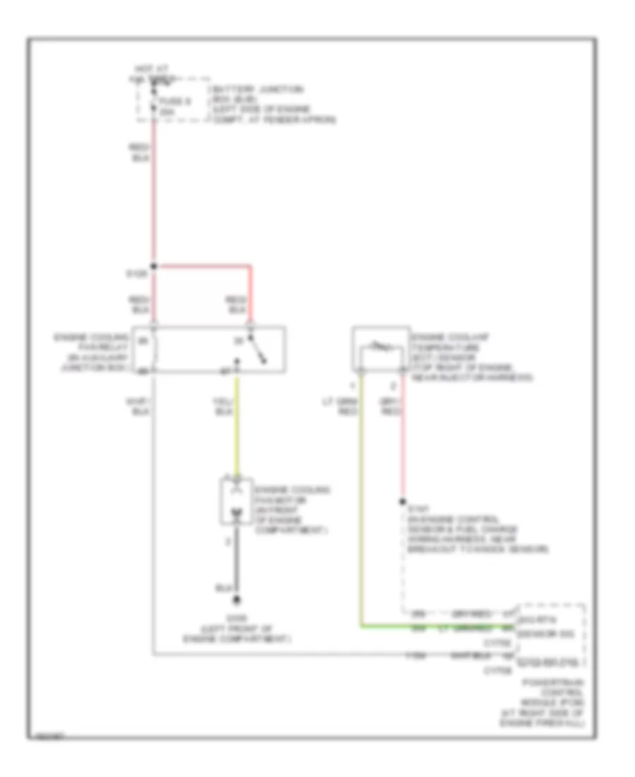
COOLING FAN
Cooling Fan Wiring Diagram for Lincoln Aviator 2004
List of elements for Cooling Fan Wiring Diagram for Lincoln Aviator 2004:

AIR CONDITIONINGANTI-LOCK BRAKESANTI-THEFTCOOLING FANCOMPUTER DATA LINESDEFOGGERSCRUISE CONTROLELECTRONIC POWER STEERINGENGINE PERFORMANCEEXTERIOR LIGHTSNAVIGATIONGROUND DISTRIBUTIONHEADLIGHTSHORNINTERIOR LIGHTSMEMORY SYSTEMSPOWER MIRRORSPOWER DISTRIBUTIONPOWER DOOR LOCKSPOWER WINDOWSINSTRUMENT CLUSTERRADIOPOWER SEATSPOWER TOP/SUNROOFSTARTING/CHARGINGTRANSMISSIONSUPPLEMENTAL RESTRAINTSSHIFT INTERLOCKWIPER/WASHERWARNING SYSTEMS