SHIFT INTERLOCK
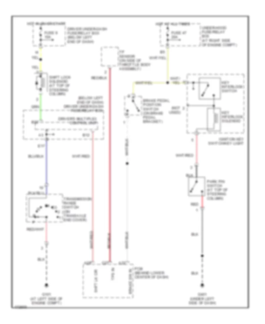
Shift Interlock Wiring Diagram for Honda Odyssey EX 2004
List of elements for Shift Interlock Wiring Diagram for Honda Odyssey EX 2004:
- (below left end of dash) driver under-dash fuse/relay box
- (not
- A28
- A32
- B12
- B22
- Brake pedal position switch (on brake pedal bracket)
- Brake sw in
- C27
- Driver under-dash fuse/relay box (below left end of dash)
- Driver's multiplex control unit
- E17
- Fuse 47 20a
- Fuse 9 10a
- G101 (at left side of engine compt)
- G401 (under left side of dash)
- Hot at all times
- Hot in on or start
- Ignition key switch/key light
- Key interlock solenoid
- Key interlock switch
- Park pin switch (at top of steering column)
- Pcm (behind lower center of dash)
- Red
- Shft lk cir
- Shift lock solenoid (at top of steering column)
- Tp sensor (on side of throttle body assembly)
- Tps in
- Transmission range switch (on transaxle end cover)
- Under-hood fuse/relay box (at right side of engine compt)
- Used)
 Čeština
 Dansk
Dansk Deutsch
 Ελληνικά
 English
 English
 Español
 Suomi
Suomi Français
 Français
 עברית
עברית Hrvatski
 Magyar
 Italiano
 日本語
日本語 한국어
한국어 Nederlands
 Polski
 Português
 Português
 Română
 Slovenčina
 Slovenščina
 Svenska
 Türkçe
 中文 (中国)
 Русский