SHIFT INTERLOCK
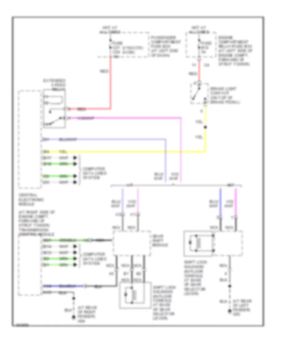
Shift Interlock Wiring Diagram for Volvo V70 R 2004
List of elements for Shift Interlock Wiring Diagram for Volvo V70 R 2004:
- (at rear of left fender) g93
- (at rear of right fender) g94
- (at right side of engine compt, forward of strut tower) transmission control module
- (in floor console, at base of gear selector lever)
- (v70/xc70) (xc90)
- A/t
- A53
- A54
- B13
- B14
- B17
- B18
- B21
- Brake light contact (on top of brake pedal)
- Central electronic module
- Computer data lines system
- Engine compartment relay/fuse box (at left side of engine compt, forward of strut tower)
- Extended x-feed relay
- Fuse b12 5a
- Fuse c21 c24 10a
- Gear shift module
- Hot at all times
- M/t
- Nca
- Passenger compartment fuse box (at left end of dash)
- Red
- Shift lock solenoid
- Shift lock solenoid (in floor console, at base of gear selector lever)
 Čeština
 Dansk
Dansk Deutsch
 Ελληνικά
 English
 English
 Español
 Suomi
Suomi Français
 Français
 עברית
עברית Hrvatski
 Magyar
 Italiano
 日本語
日本語 한국어
한국어 Nederlands
 Polski
 Português
 Português
 Română
 Русский
 Slovenščina
 Svenska
 Türkçe
 中文 (中国)
 Slovenčina