POWER DISTRIBUTION
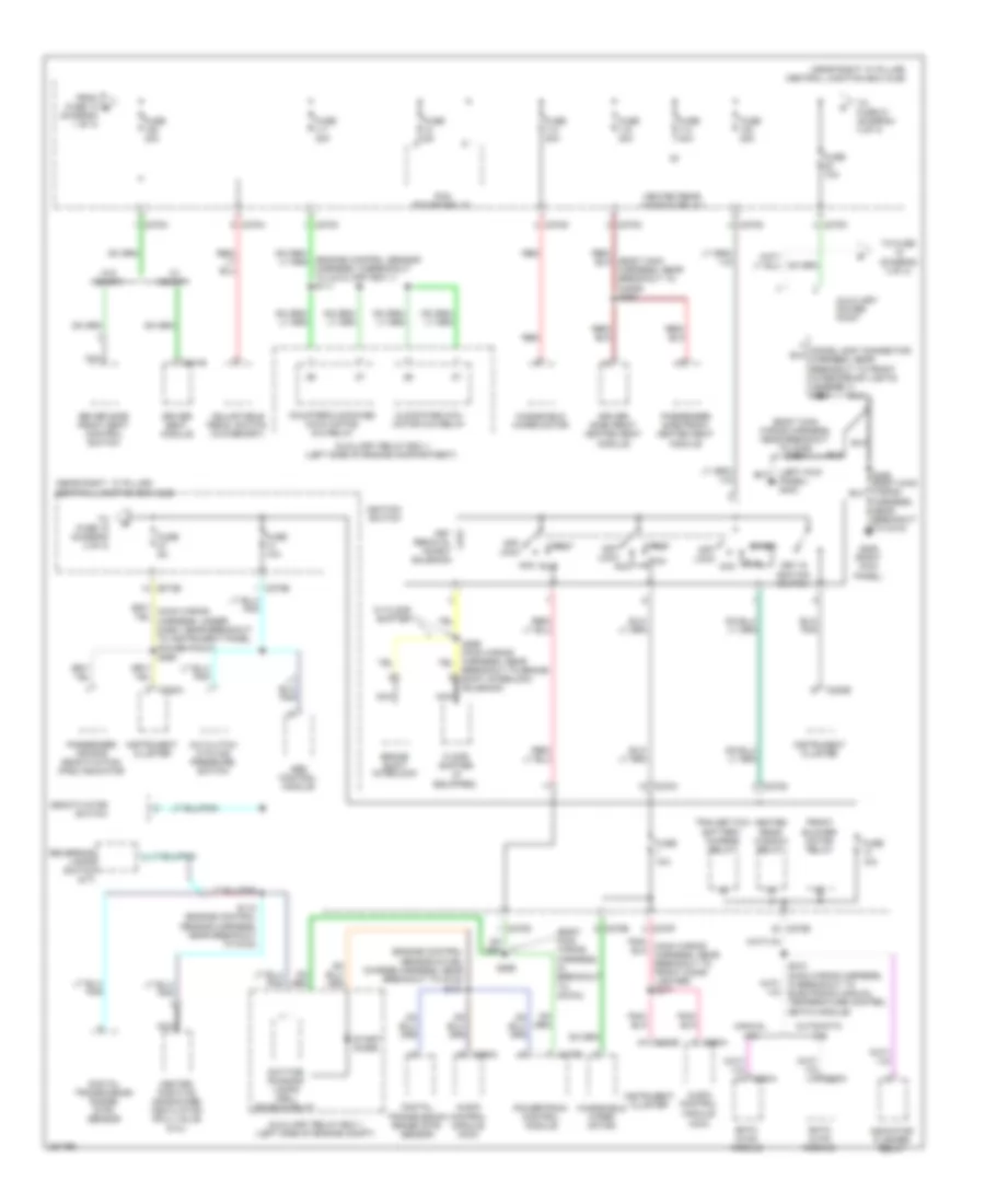
Power Distribution Wiring Diagram (1 of 3) for Ford Pickup F150 2008
 https://portal-diagnostov.com/license.html
Automotive Electricians Portal FZCO
Automotive Electricians Portal FZCO
https://portal-diagnostov.com/license.html
https://portal-diagnostov.com/license.html
Automotive Electricians Portal FZCO
Automotive Electricians Portal FZCO
List of elements for Power Distribution Wiring Diagram (1 of 3) for Ford Pickup F150 2008:
- (acm)
- (body main wiring harness, in breakout for central junction box (cjb)
- (diagram 1 of 3)
- (early production:
- (engine control sensor harness, near breakout to c139)
- (main wiring harness, near breakout to autolamp/ sunload sensor) s266
- (sdars) module
- (seat control feed jumper harness, near breakout to driver seat module) s315
- (w/ 4x4) s105
- (w/ memory)
- A/c clutch relay
- Abs control module
- Audio control module
- Autolamp/ sunload sensor
- Automatic a/c
- Auxiliary relay box 1 (left side of engine compt)
- Battery
- Battery saver relay
- Brake pedal position switch
- Breakout to c339) s338
- C102a
- C175b
- C205a
- C228a
- C270b
- C270c
- C270d
- C270e
- C270f
- C270g
- C270h
- C270j
- C270m
- C270n
- C270p
- C290a
- C294a
- C3008a
- C341c
- Central junction box (cjb) (near right ``a" pillar)
- Console 1 power point (w/ center console)
- Console 2 power point (w/o center console)
- Data link connector (dlc)
- Driver seat module
- Driver side front seat control switch
- Eatc hvac module
- Emtc hvac module
- Engine control sensor harness, near breakout to g102) (late production: engine control sensor harness, near breakout to integrated wheel ends solenoid)
- Evap canister vent control solenoid
- Exterior rear view mirror switch
- From fuse 5 a
- Front blower motor relay
- Front cigar lighter
- Fuse 10a
- Fuse 15a
- Fuse 20a
- Fuse 25a
- Fuse 30a
- Fuse 40a
- Fuse 7.5a
- G202 (left front footwell)
- G206 (right kick panel)
- Generator
- Horn relay
- Indicator flasher relay
- Instrument panel power point
- Integrated wheel ends solenoid (w/ 4x4)
- Main light switch
- Manual a/c
- Nca
- Passenger side front seat control switch
- Power folding mirror module
- Powertrain control module (pcm)
- Rear entertainment module
- Red
- Red/ s211
- S113
- S120 (alternator rectifier harness, near breakout to fusible link a, b or c)
- S201
- S203
- S209 (main wiring harness, near breakout to audio unit)
- S236 (main wiring harness, near breakout to c286)
- S345 (w/ memory) (body main wiring harness, near breakout to c312)
- S355
- S380
- Satellite digital audio receiver system
- Starter motor
- Starter relay
- Subwoofer
- To fuse 109 (diagram 2 of 3)
- To fuse 6 (diagram 1 of 3)
- Trailer brake control module
- Trailer tow battery charge relay
- Trailer tow parking lamp relay
- Trailer tow reversing lamp relay
- Vehicle security module
- W/ satellite radio
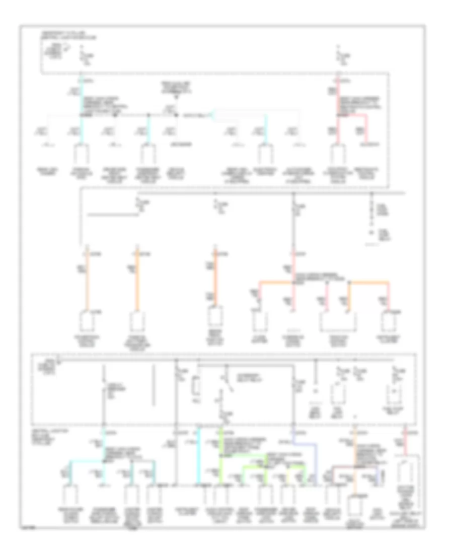
Power Distribution Wiring Diagram (2 of 3) for Ford Pickup F150 2008
 https://portal-diagnostov.com/license.html
Automotive Electricians Portal FZCO
Automotive Electricians Portal FZCO
https://portal-diagnostov.com/license.html
https://portal-diagnostov.com/license.html
Automotive Electricians Portal FZCO
Automotive Electricians Portal FZCOList of elements for Power Distribution Wiring Diagram (2 of 3) for Ford Pickup F150 2008:
- (acm)
- (body main harness, near breakout to c3206) s320
- (body main wiring harness, in breakout to c270a)
- (body main wiring harness, near breakout to c339) s340
- (diagram 1 of 3)
- (engine control sensor & fuel charge harness, near breakout to g102) s124
- (engine control sensor harness, in breakout to auxiliary box 1) s111
- (left kick panel) g303
- (near right "a" pillar) central junction box (cjb)
- (near right ``a" pillar) central junction box (cjb)
- A/c clutch cycling pressure switch
- Abs control module
- Acc
- Adjustable pedal switch (w/o memory)
- Audio control module
- Audio control module (acm)
- Automatic a/c
- Auxiliary power point
- Auxiliary relay box 1 (left side of engine compartment)
- Auxiliary relay box 1 (left side of engine compt)
- Brake shift interlock
- Breakout to brake shift interlock solenoid)
- C175b
- C220a
- C220b
- C270b
- C270c
- C270d
- C270e
- C270f
- C270g
- C270h
- C270k
- C270m
- C290a
- C341b
- Clockwise (cw) motor 4x4 relay
- Counterclockwise (ccw) motor 4x4 relay
- Daytime running lamps (drl) enable relay
- Deactivator switch
- Digital transmission range (dtr) sensor
- Driver seat module
- Driver side front heated seat module
- Driver side front seat control switch
- Eatc hvac module
- Emtc hvac module
- Floor shifter (if equipped)
- From fuse 10 b
- Front blower motor relay
- Fuse 10a
- Fuse 20a
- Fuse 30a
- Fuse 40a
- Fuse 5a
- G206 (right kick panel)
- Heated positive crankcase ventilation (pcv) valve (5.4l)
- Heated rear window relay
- Ignition switch
- Indicator flasher relay
- Instrument cluster
- Key in ignition switch
- Key removal inhibit solenoid
- Manual a/c
- Nca
- Off/ lock
- Passenger air bag deactivation (pad) indicator
- Passenger side front heated seat module
- Pcm power relay
- Powertrain control module
- Red
- Reversing lamps switch (m/t)
- Run
- S112 (engine control sensor harness, near breakout to g102)
- S210 (main wiring harness, in breakout to electronic manual temperature control (emtc) module)
- S298
- S355 (body main wiring harness, near breakout to c312)
- S905
- Start
- Start diode
- To fuse (diagram 3 of 3)
- To fuse 18 (diagram 3 of 3)
- To fuse 21 (diagram 3 of 3)
- Trailer tow battery charge relay
- W/ floor shifter
- W/ memory
- W/o memory
- Windshield wiper motor
Power Distribution Wiring Diagram (3 of 3) for Ford Pickup F150 2008
 https://portal-diagnostov.com/license.html
Automotive Electricians Portal FZCO
Automotive Electricians Portal FZCO
https://portal-diagnostov.com/license.html
https://portal-diagnostov.com/license.html
Automotive Electricians Portal FZCO
Automotive Electricians Portal FZCOList of elements for Power Distribution Wiring Diagram (3 of 3) for Ford Pickup F150 2008:
- (body main harness, near breakout to restraints control module) s323
- (body main wiring harness, near breakout to c312) s344
- (body main wiring harness, near breakout to central junction box (cjb)) s228
- (diagram 2 of 3)
- (main wiring harness, near breakout to c2026) s225
- (main wiring harness, near breakout to instrument panel power point) s285
- (near right "a" pillar) central junction box (cjb)
- Accessory delay relay
- Audio control module (acm) (xlt, fx4, lariat)
- Auto-dimmer interior mirror unit (if equipped)
- Auxiliary relay box 1 (left side of engine compt)
- Brake pedal position switch
- C175b
- C202b
- C2150a
- C220b
- C270b
- C270d
- C270e
- C270f
- C270h
- C270j
- C270m
- C270n
- C290a
- C3008a
- C3008b
- C310a
- C504b
- Central junction box (cjb) (near right "a" pillar)
- Circuit breaker 30a
- Daytime running lamps (drl) enable relay
- Driver side door lock switch
- Driver side front heated seat module
- Electronic compass
- Floor shifter
- Fog lamp relay
- From auxiliary power point (diagram 2 of 3)
- From c fuse 102 (diagram 2 of 3)
- From fuse 27 d
- Fuel pump diode
- Fuel pump relay
- Fuse 10a
- Fuse 15a
- Fuse 20a
- Fuse 5a
- High beam relay
- Instrument cluster
- Main light switch
- Master window adjust switch
- Master window adjust switch (regular cab)
- Multi- function switch
- Nca
- Occupant classification system module
- Overdrive cancel switch
- Parking aid module (pam)
- Passenger side door lock switch
- Passenger side front heated seat module
- Passenger side window adjust switch (regular cab)
- Passive anti-theft transceiver module
- Powertrain control module
- Rear power sliding window switch
- Rear view camera
- Rear view camera display mirror (if equipped)
- Restraints control module
- Roof opening panel module
- Roof opening panel switch
- Tan/ red
- Traction control switch
- Vehicle security module

 Čeština
 Dansk
Dansk Deutsch
 Ελληνικά
 English
 English
 Español
 Suomi
Suomi Français
 Français
 עברית
עברית Hrvatski
 Magyar
 Italiano
 日本語
日本語 한국어
한국어 Nederlands
 Polski
 Português
 Português
 Română
 Русский
 Slovenčina
 Slovenščina
 Svenska
 中文 (中国)
