DEFOGGERS
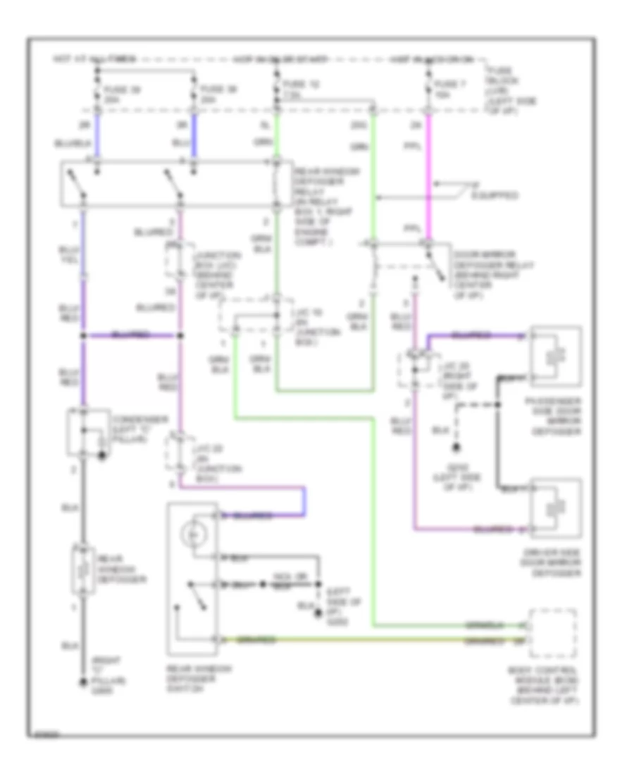
Defogger Wiring Diagram for Nissan Maxima GXE 1997
List of elements for Defogger Wiring Diagram for Nissan Maxima GXE 1997:
- (left side of i/p) g202
- (right "c" pillar) g905
- 20g
- Body control module (bcm) (behind left center of i/p)
- Condenser (left "c" pillar)
- Door mirror defogger relay (behind right center of i/p)
- Driver side door mirror defogger
- Fuse 12 7.5a
- Fuse 38 20a
- Fuse 39 20a
- Fuse 7 10a
- Fuse block (j/b) (left side of i/p)
- G202 (left side of i/p)
- Hot at all times
- Hot in acc or on
- Hot in on or start
- If equipped
- J/c 10 (in junction box)
- J/c 20 (right side of i/p)
- J/c 22 (in junction box)
- Junction box (j/c) (behind center of i/p)
- Passenger side door mirror defogger
- Rear window defogger
- Rear window defogger relay (in relay box 1, right side of engine compt.)
- Rear window defogger switch
 English