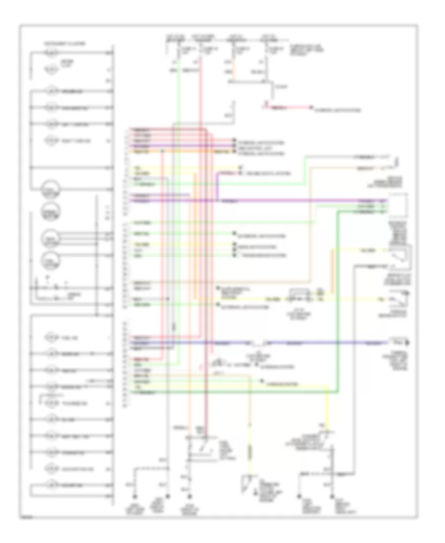
INSTRUMENT CLUSTER
Instrument Cluster Wiring Diagram for Nissan Maxima GXE 1997
List of elements for Instrument Cluster Wiring Diagram for Nissan Maxima GXE 1997:
- Abs control unit
- Abs ind
- Airbag ind
- Brake fluid level switch (in reservoir)
- Brake ind
- Charge ind
- Charging system
- Clock
- Cruise contol system
- Cruise ind
- Door ind
- Ecm eccs control module (behind center console)
- Exterior lights system
- Fuel gauge
- Fuel ind
- Fuel tank gauge unit (in tank)
- Fuse 13 10a
- Fuse 19 7.5a
- Fuse 21 10a
- Fuse 40 7.5a
- Fuse block (j/b) (below left side of dash)
- G107 (behind right headlight)
- G108 (left radiator support)
- G125 (front of engine)
- G16
- G201 (right side of dash)
- G202 (left side of dash)
- Headlights system
- High beam ind
- Hot at all times
- Hot in acc or on
- Hot in on or start
- Hot in park or head
- Instrument cluster
- Interior lights system
- J/c (top center of dash)
- J/c 11
- J/c 16 (top center of dash)
- Left turn ind
- Malfunction ind
- Meter illum.
- O/d off ind
- Oil ind
- Oil pressure switch (lower left front of engine)
- Parking brake switch
- Right turn ind
- Seat belt ind
- Speed- ometer
- Tach- ometer
- Temp. gauge
- Thermal transmitter (top left front of engine)
- Transmissions system
- Vehicle speed sensor (on transmission)
- Warning system
- Washer ind
- Washer level switch (in washer fluid reservoir)
 English