TRANSMISSION
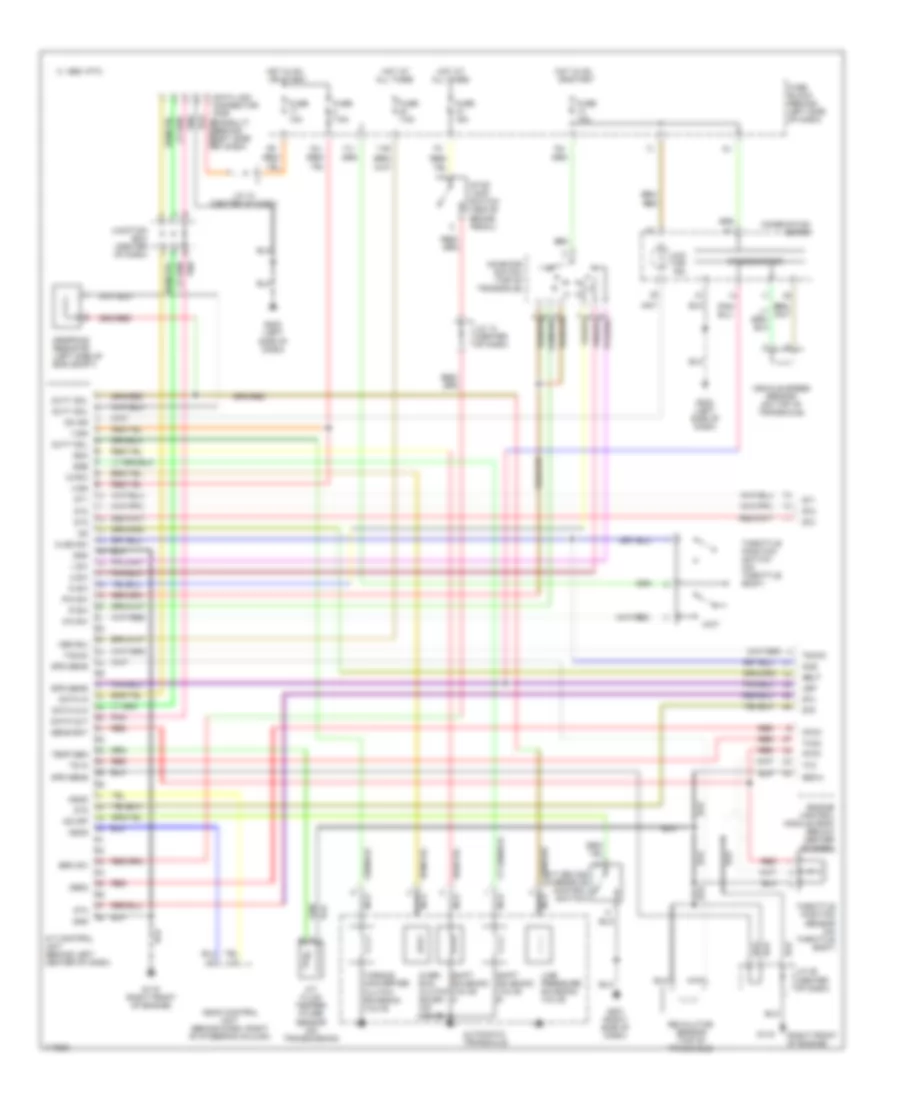
A/T Wiring Diagram for Nissan Maxima GXE 1997
List of elements for A/T Wiring Diagram for Nissan Maxima GXE 1997:
- (right front of engine)
- 1 sw
- 13g
- 17j
- 18j
- 1995 vftc c
- 19j
- 2 sw
- A/t control unit (behind left center of dash)
- A/t device (overdrive control switch)
- A/t fluid temper- ature sensor (on transmission)
- All times
- Ascd
- Ascd control unit (behind dash, right of steering column)
- Atck
- Automatic transaxle
- Avcc
- Brk sw
- Clsd sw
- Combination meter
- D sw
- Data clk
- Data in
- Data link connector (for consult) (behind left side of dash)
- Data out
- Dropping resistor (left side of eng compt)
- Dt1
- Dt2
- Dt3
- Dt4
- Dt5
- Duty sol
- Engine control module (ecm) (below center of dash)
- Fuse 10a
- Fuse 15a
- Fuse 7.5a
- Fuse block (behind left side of dash)
- G119
- G119 (right front of engine)
- G201 (right side of dash)
- G202 (left side of dash)
- Gnd
- Gnd-a
- Hot at
- Hot in on or start
- Idle
- Inhibitor switch (top of transaxle)
- J/c 10 (center of dash)
- J/c 13 (center of dash)
- J/c 25 (center of dash)
- Junction box (center of dash)
- Line pressure solenoid valve
- Mem b/u
- Nca
- Neut
- O/d off ind
- Obd2
- Od ind
- Od off
- Over- run clutch solen- oid valve
- Ovr/c
- P/n sw
- Pnk
- R sw
- Red
- Revolution sensor (top of transaxle)
- Sens bat
- Shift solenoid valve a
- Shift solenoid valve b
- Spd sens
- Speedometer
- Ssa
- Ssb
- Stop lamp switch (above brake pedal)
- Tacho
- Temp sen
- Throttle position sensor (on throttle body)
- Throttle position switch (on throttle body)
- Torque converter clutch solenoid valve
- Ts in
- Tvo
- Tvoo
- Vehicle speed sensor (on top of transaxle)
- Vign
- Vsp
- Wo sw
- Wot
 English