
SUPPLEMENTAL RESTRAINTS
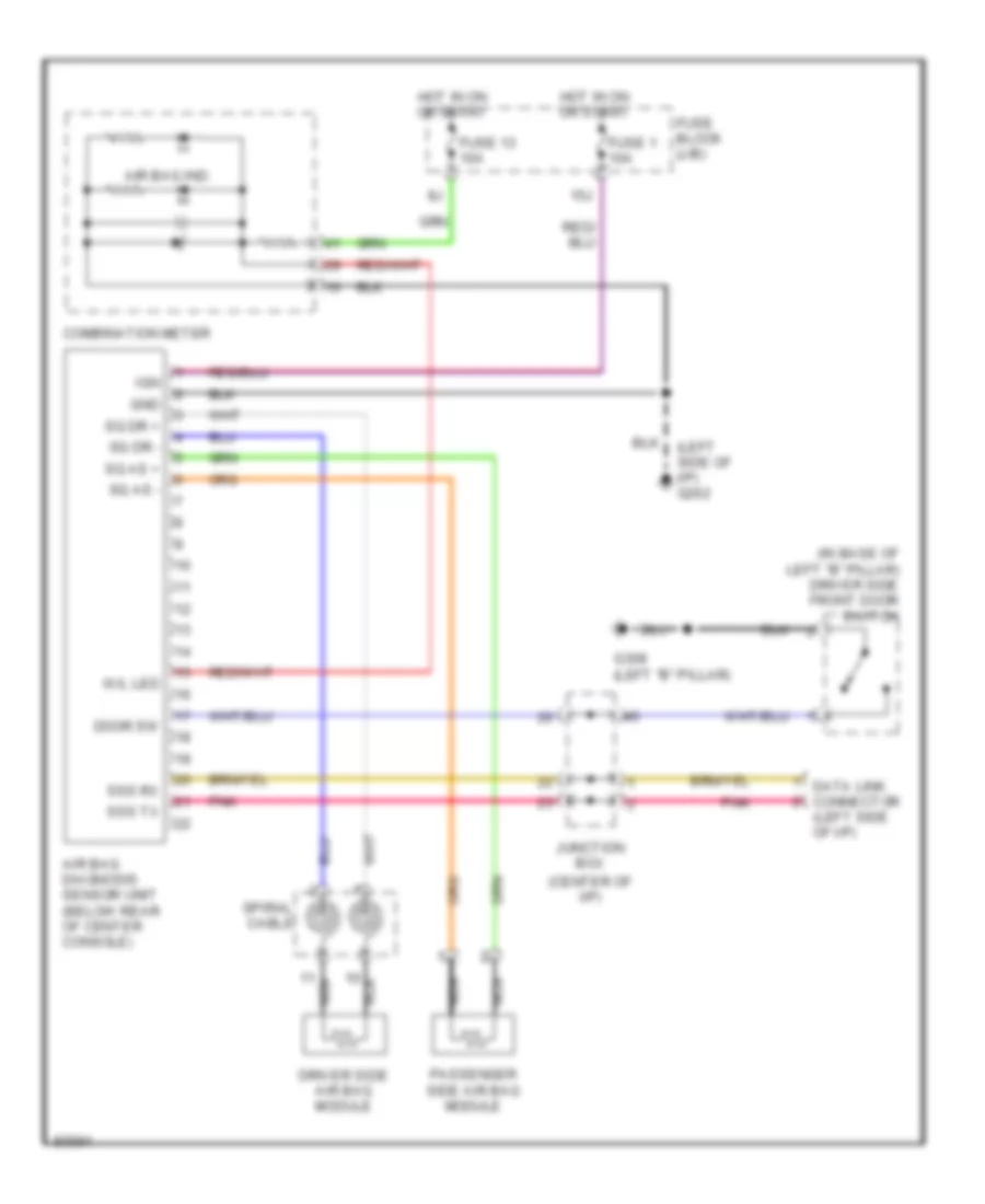
Supplemental Restraint Wiring Diagram for Nissan Maxima GXE 1997
List of elements for Supplemental Restraint Wiring Diagram for Nissan Maxima GXE 1997:
BODY COMPUTERAIR CONDITIONINGCOMPUTER DATA LINESANTI-LOCK BRAKESCRUISE CONTROLCOOLING FANANTI-THEFTEXTERIOR LIGHTSGROUND DISTRIBUTIONHEADLIGHTSDEFOGGERSINSTRUMENT CLUSTERPOWER DOOR LOCKSENGINE PERFORMANCEHORNPOWER ANTENNAINTERIOR LIGHTSPOWER MIRRORSRADIOPOWER DISTRIBUTIONPOWER WINDOWSPOWER SEATSSHIFT INTERLOCKSSTARTING/CHARGINGSUPPLEMENTAL RESTRAINTSPOWER TOP/SUNROOFTRANSMISSIONWARNING SYSTEMSWIPER/WASHERTRUNK, TAILGATE, FUEL DOOR