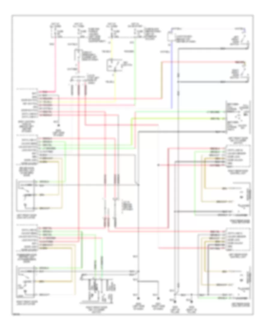
POWER DOOR LOCKS
Power Door Lock Wiring Diagram for Nissan Maxima GXE 1997
List of elements for Power Door Lock Wiring Diagram for Nissan Maxima GXE 1997:
- And n
- Bat
- Between
- Between full stroke and n
- Body control module (behind left center of dash)
- Circuit breaker 2 (under left end of dash)
- Data line a1
- Data line a2
- Door lock
- Door lock status
- Door switch
- Door unlock
- Driver door control unit (in driver's door)
- Full between
- Full stroke
- Fuse 7.5a
- Fuse and fusible link box (left side of engine compartment)
- Fuse block (behind dash, left of steering column)
- Fuse f 30a
- G10
- G201 (right side of dash)
- G202 (left side of dash)
- G305 (right "b" pillar)
- G308 (left "b" pillar)
- Gnd
- Grd
- Hot at all times
- Hot in on or start
- Ign
- J/c 15 (behind center of dash)
- J/c 23 (top left side of dash)
- Junction box (behind top center of dash)
- Key switch
- Left front door key cylinder switch
- Left front door lock actuator
- Left front door switch
- Left rear door control unit
- Left rear door lock actuator
- Lock
- Lock sw
- Lock switch
- Locked
- Off
- Passenger door control unit (in passenger's door)
- Pnk
- Right front door key cylinder switch
- Right front door lock actuator
- Right front door switch
- Right rear door control unit
- Right rear door lock actuator
- Status door lock
- Stroke and n
- Un- lock
- Unlock
- Unlock sens
- Unlock sensor
- Unlock switch
- Unlocked
 English