CRUISE CONTROL
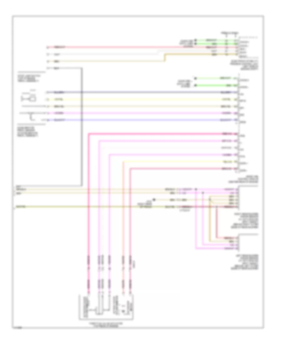
Cruise Control Wiring Diagram (1 of 2) for Mercedes-Benz CLS550 2014

List of elements for Cruise Control Wiring Diagram (1 of 2) for Mercedes-Benz CLS550 2014:
- (left front footwell) w15/5
- Accelerate & set switch
- C12i
- C14i
- C2i
- C5c
- C7i
- Can c h
- Can c l
- Can e h
- Can e l
- Can e l a
- Can h h
- Can h l
- Computer data lines system
- Cruise control lever
- Decelerate & set switch
- Distronic control (if equipped)
- Distronic control unit
- Distronic electric controller unit (center front of engine compt)
- Distronic radar sensor
- Front sam control unit w/ fuse & relay module (left rear of engine compt)
- Fully integrated transmission control control unit (in transmission)
- Fuse 5a
- Fuse 7.5a
- Hot at all times
- Hot w/ chassis circuit 87 relay energized
- Hot w/ circuit 15 relay energized
- Indicator switch
- Instrument cluster
- Left front bumper distronic sensor (dtr) (if equipped) (behind left side of front bumper)
- Lvds n
- Lvds p
- Multi-function camera (w/ active lane keeping assist) (top center of front windshield)
- Nca
- Off switch
- Output shaft rpm sensor
- Rear sam control unit w/ fuse & relay module (right side of trunk)
- Red
- Resume from memory switch
- Right front bumper distronic sensor (dtr) (if equipped) (behind right side of front bumper)
- Sh high
- Sh low
- Steering column module control unit (top of steering column)
- Sv high
- Video & radar sensor system control unit (right front footwell)
- Video n
- Video p
- W/ short range radar & active park assist
- W/ short range radar w/o active park assist
- W15/1 (right front footwell)
- W2 (right front of engine compt)
- X26/38-c1
- X26/38-c3
Cruise Control Wiring Diagram (2 of 2) for Mercedes-Benz CLS550 2014
List of elements for Cruise Control Wiring Diagram (2 of 2) for Mercedes-Benz CLS550 2014:
- (-)
- +5v
- Accelerator pedal sensor (in accelerator pedal assembly)
- Basic
- Bls h
- Bls l
- Bls m
- Can e h
- Can e l
- Can-e h
- Can-e l
- Computer data lines system
- Dcpm +
- Dcpm -
- Electronic stability program control unit (left side of engine compt)
- Ip1s
- Ip2s
- Left rear bumper radar sensor (w/ active blind spot assist) (behind left outer edge of rear bumper)
- Me-sfi (me) control module (center rear of engine)
- Motor actuator
- Potentiometer 2 actuator value
- Potentiometer actual valve
- Premium
- Right rear bumper radar sensor (w/ active blind spot assist) (behind right outer edge of rear bumper)
- Sp1
- Sp1s
- Sp2
- Sp2s
- Stop lamp switch (top of brake pedal assembly)
- Throttle valve actuator (top rear of engine)
- W7/8 (right rear of trunk)
- X172/2-c1
- X26-c3