TRANSMISSION
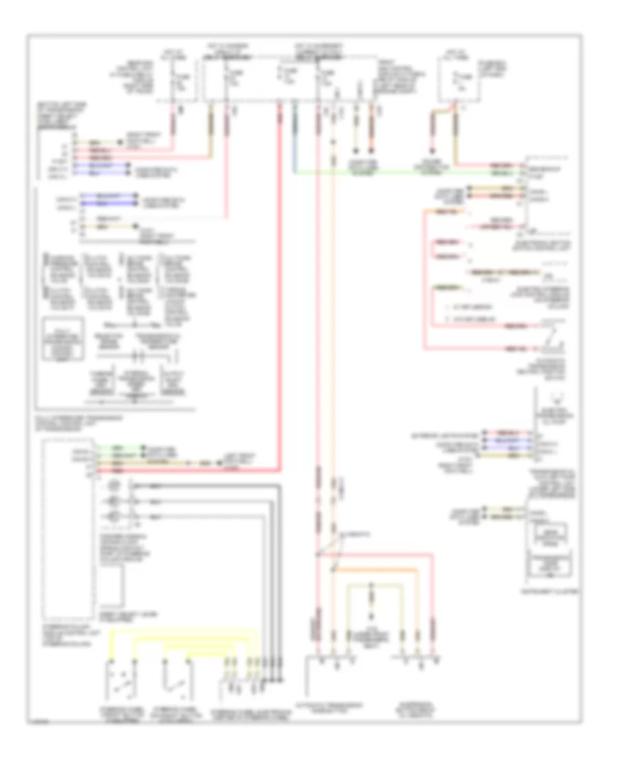
Transmission Wiring Diagram for Mercedes-Benz CLS550 2014
List of elements for Transmission Wiring Diagram for Mercedes-Benz CLS550 2014:
- (bottom left side of transmission) direct select intelligent servo module
- (left front footwell) w15/5
- (right front footwell) w15/1
- 30z
- Automatic transmission mode button
- Automatic transmission neutral position switch
- C17c
- C22i
- C5c
- C9g
- Can b h
- Can b l
- Can c h
- Can c l
- Can e h
- Can e l
- Can-c h
- Can-c l
- Clutch control solenoid valve k1
- Clutch control solenoid valve k2
- Clutch control solenoid valve k3
- Computer data lines system
- Direct select lever (if equipped)
- Electric steering lock control module (on steering column)
- Electric transmission oil pump
- Electronic ignition switch control unit
- Exterior lights system
- Ezs backup
- Fanfare horns & air bag clock spring contact (part of steering column module)
- Front sam control module w/ fuse & relay module (left rear of engine compt)
- Fully integrated transmission control control unit
- Fully integrated transmission control control unit (in transmission)
- Fuse 10a
- Fuse 15a
- Fuse 5a
- Fuse 7.5a
- Fuse box (left end of dash)
- Gear indicator (prnd)
- Gnd
- Hot at all times
- Hot w/ chassis circuit 87 relay energized
- Hot w/ quiescent current cutout relay energized
- Instrument cluster
- Internal transmission speed rpm sensor
- Ism
- Lin 1
- Lsp+
- Lsp-
- Multidisk brake control solenoid valve b1
- Multidisk brake control solenoid valve b2
- Multidisk brake control solenoid valve b3
- Output shaft rpm sensor
- P not
- Power distribution system
- Rear sam control unit w/ fuse & relay module (right side of trunk)
- Red
- Selection range sensor
- Steering column module control unit (top of steering column)
- Steering wheel downshift button (if equipped)
- Steering wheel electronics (center of steering wheel)
- Steering wheel upshift button (if equipped)
- Suspension button group (w/ airmatic)
- Torque converter lockup clutch control solenoid valve
- Transmission mode display (s)
- Transmission oil auxiliary pump control unit (lower left side of transmission)
- Transmission oil temperature sensor
- Turbine wheel rpm sensor
- W/ airmatic
- W/ keyless go
- W/o keyless go
- W15/1 (right front footwell)
- W19 (under front passenger's seat)
- Working pressure control solenoid valve
- X138/1-c1
- X190-c1
 English