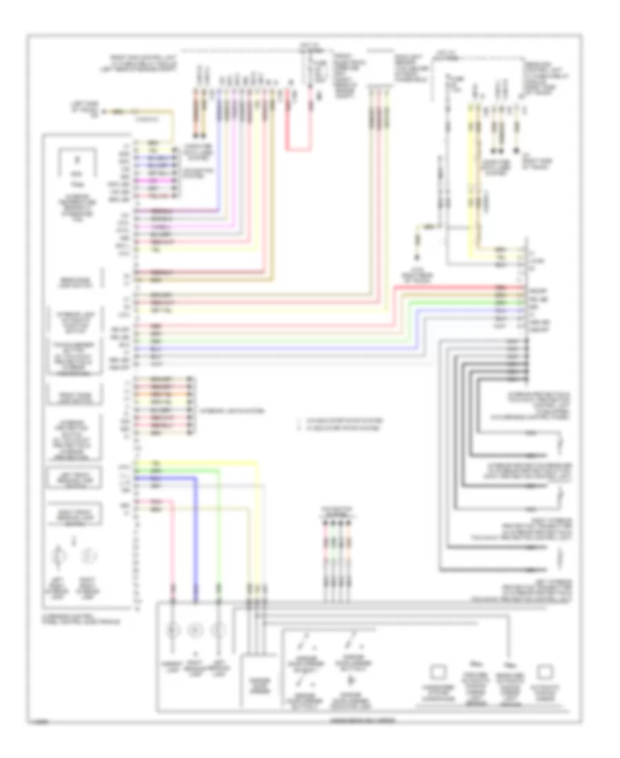
INSTRUMENT CLUSTER
Instrument Cluster Wiring Diagram for Mercedes-Benz CLS550 2014

List of elements for Instrument Cluster Wiring Diagram for Mercedes-Benz CLS550 2014:
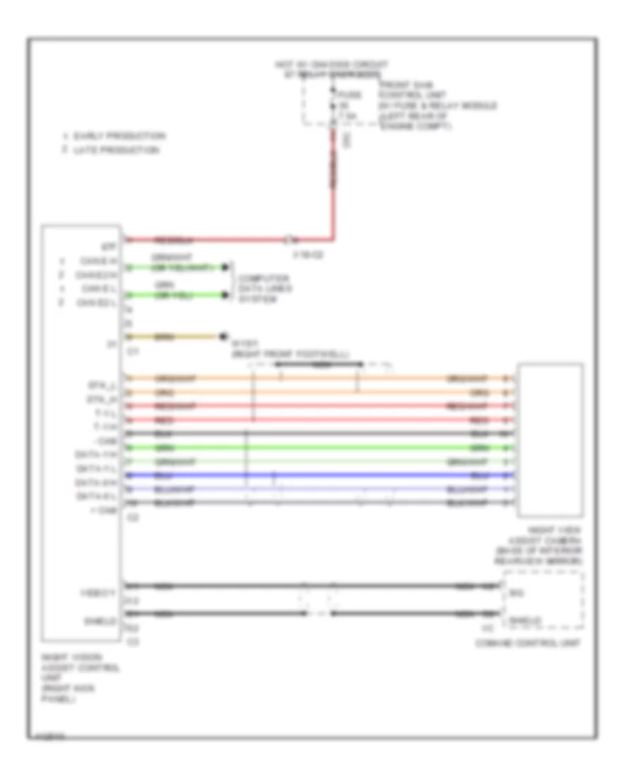
Night Vision Wiring Diagram for Mercedes-Benz CLS550 2014
List of elements for Night Vision Wiring Diagram for Mercedes-Benz CLS550 2014:
Overhead Console Wiring Diagram, with Sunroof for Mercedes-Benz CLS550 2014
List of elements for Overhead Console Wiring Diagram, with Sunroof for Mercedes-Benz CLS550 2014:
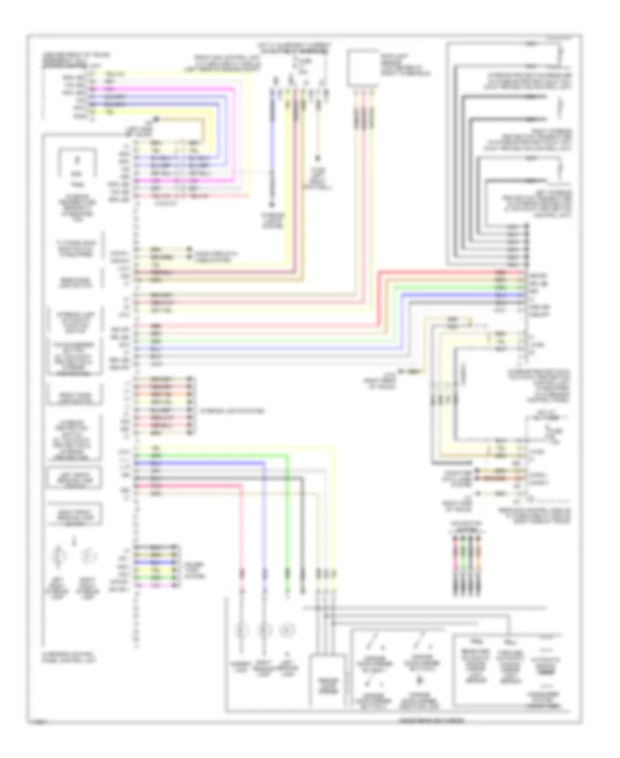
Overhead Console Wiring Diagram, without Sunroof for Mercedes-Benz CLS550 2014
List of elements for Overhead Console Wiring Diagram, without Sunroof for Mercedes-Benz CLS550 2014: