ENGINE ACCESSORIES
Stationary Heater Wiring Diagram for Mercedes-Benz CLS550 2014
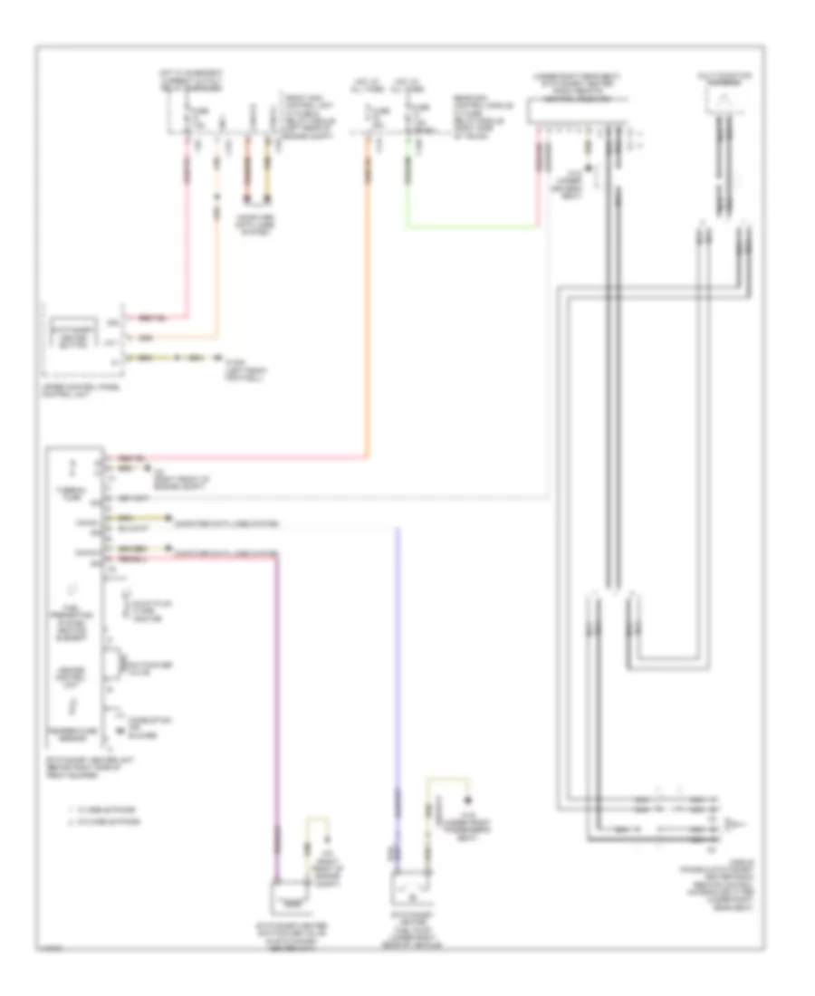
List of elements for Stationary Heater Wiring Diagram for Mercedes-Benz CLS550 2014:
- (under right rear seat) stationary heater radio remote control receiver
- 30g
- C14i
- C15h
- C17c
- C22i
- C5c
- Can b h
- Can b l
- Combustion air blower
- Computer data lines system
- Front sam control unit w/ fuse & relay module (left rear of engine compt)
- Fuel preheating system heating element
- Fuse 20a
- Fuse 7.5a
- Fuse 7.5a (or 5a)
- Glow plug flame monitor
- Heater control unit
- Hot at all times
- Hot w/ quiescent current cutout relay energized
- Lin 1
- Mobile phone & stationary heater radio remote control antenna splitter (under right rear seat)
- Multi-function antenna
- Nca
- Rear sam control module w/ fuse/ relay module (right side of trunk)
- Sig
- Stationary heater button
- Stationary heater fuel pump (under right rear of vehicle)
- Stationary heater switchover valve (in stationary heater unit)
- Stationary heater unit (behind right side of front bumper)
- Switchover valve
- Temperature sensor
- Thermal fuse
- Upper control panel control unit
- W/ mobile phone
- W/o mobile phone
- W15/5 (left front footwell)
- W18 (under driver's seat)
- W19 (under front passenger's seat)
- W2 (right front of engine compt)
- X nca
- X62/33-c2
 English