WARNING SYSTEMS
Seat Belt Warning Wiring Diagram for Mercedes-Benz CLS550 2014

List of elements for Seat Belt Warning Wiring Diagram for Mercedes-Benz CLS550 2014:
- (left front footwell) w15/2
- (left front footwell) w15/5
- (right front of engine compt)
- (under front of center console) w26
- 30g
- Bbv hr
- Bbv vl
- Bfs
- Brake fluid level switch (on brake fluid reservoir)
- C11c
- C15m
- C19i
- C20m
- C22i
- C5c
- Can b h
- Can b l
- Can e h
- Can e l
- Computer data lines system
- Driver seat belt buckle restraint systems switch
- Front sam control unit w/ fuse & relay module (left rear of engine compt)
- Fuse 7.5a
- Gnd
- Gss, fa
- Hot at all times
- Hot w/ quiescent current cutout relay energized
- Instrument cluster
- Left front door control unit (left front door)
- Left front door lock
- Multi-function display
- Nca
- Parking brake indicator switch (base of parking brake pedal assembly)
- Return line
- Right front brake wear sensor (on right front brake assembly)
- Right rear brake wear sensor (on right rear brake assembly)
- Rotary tumbler switch
- Seat belt warning ind lamp
- Service brake ind lamp
- Sig
- W15/5 (left front foot- well)
- W19 (under front passenger's seat)
- Warning buzzer
- X62/33-c1
- X62/6-c1
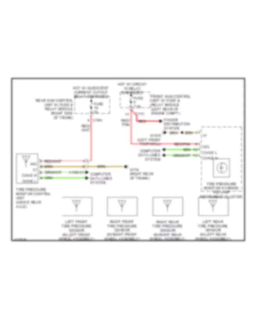
Tire Pressure Monitoring Wiring Diagram for Mercedes-Benz CLS550 2014
List of elements for Tire Pressure Monitoring Wiring Diagram for Mercedes-Benz CLS550 2014:
- 15g
- C11c
- C15h
- Can-e h
- Can-e l
- Computer data lines system
- Front sam control unit w/ fuse & relay module (left rear of engine compt)
- Fuse 5a
- Fuse 7.5a
- Hot w/ circuit 15 relay energized
- Hot w/ quiescent current cutout relay energized
- Instrument cluster
- Left front tire pressure sensor (in left front wheel assembly)
- Left rear tire pressure sensor (in left rear wheel assembly)
- Power distribution system
- Rear sam control unit w/ fuse & relay module (right side of trunk)
- Red
- Red/ pnk
- Red/pnk
- Right front tire pressure sensor (in right front wheel assembly)
- Right rear tire pressure sensor (in right rear wheel assembly)
- Tire pressure monitor control unit (above rear axle)
- Tire pressure monitor warning ind lamp
- W15/5 (left front footwell)
- W7/8 (right rear of trunk)
- X1/60-c1