NAVIGATION
Mobile Telematic System Wiring Diagram for Hyundai Veloster 2014
 https://portal-diagnostov.com/license.html
Automotive Electricians Portal FZCO
Automotive Electricians Portal FZCO
https://portal-diagnostov.com/license.html
https://portal-diagnostov.com/license.html
Automotive Electricians Portal FZCO
Automotive Electricians Portal FZCO
List of elements for Mobile Telematic System Wiring Diagram for Hyundai Veloster 2014:
- (below right
- (right center
- A/bag
- A/v & navigation head unit
- Acc/on in
- Audio
- Audio (+)
- Audio (-)
- Audio out (+)
- Audio out (-)
- Bcm rx
- Bcm tx
- C-can hi
- C-can lo
- Cluster fuse 10a
- Computer
- Computer data lines system
- Crash
- Crash in
- Data lines
- Exterior lights system
- Fuse 10a
- Gm01 (top left
- Gm01 (top left side of dash)
- Gm04
- Gnd
- Hot at all times
- Hot in acc or on
- Hot in on or start
- I/p-c
- I/p-e
- I/p-g
- Ig 1
- Ill (+)
- Ill (-)
- Inside mirror
- Ips control module
- Joint connector ura
- Keypad gnd
- Keypad in
- L mts rx
- Leak current autocut device
- M-can hi
- M-can lo
- M02-a
- M02-m
- M51
- Mem power
- Mic (+)
- Mic (-)
- Mic (left front of roof)
- Mic in (+)
- Mic in (-)
- Mic out (+)
- Mic out (-)
- Mic shield
- Mr11
- Mts module
- Multi media fuse 15a
- Nca
- O mts tx
- Of dash)
- On/start in
- Red
- Reverse sig
- Rx (+)
- Rx (-)
- Shield gnd
- Side of dash)
- Sig
- Smart junction box
- Srs control module (under floor console)
- System
- Tx (+)
- Tx (-)
- Unlock
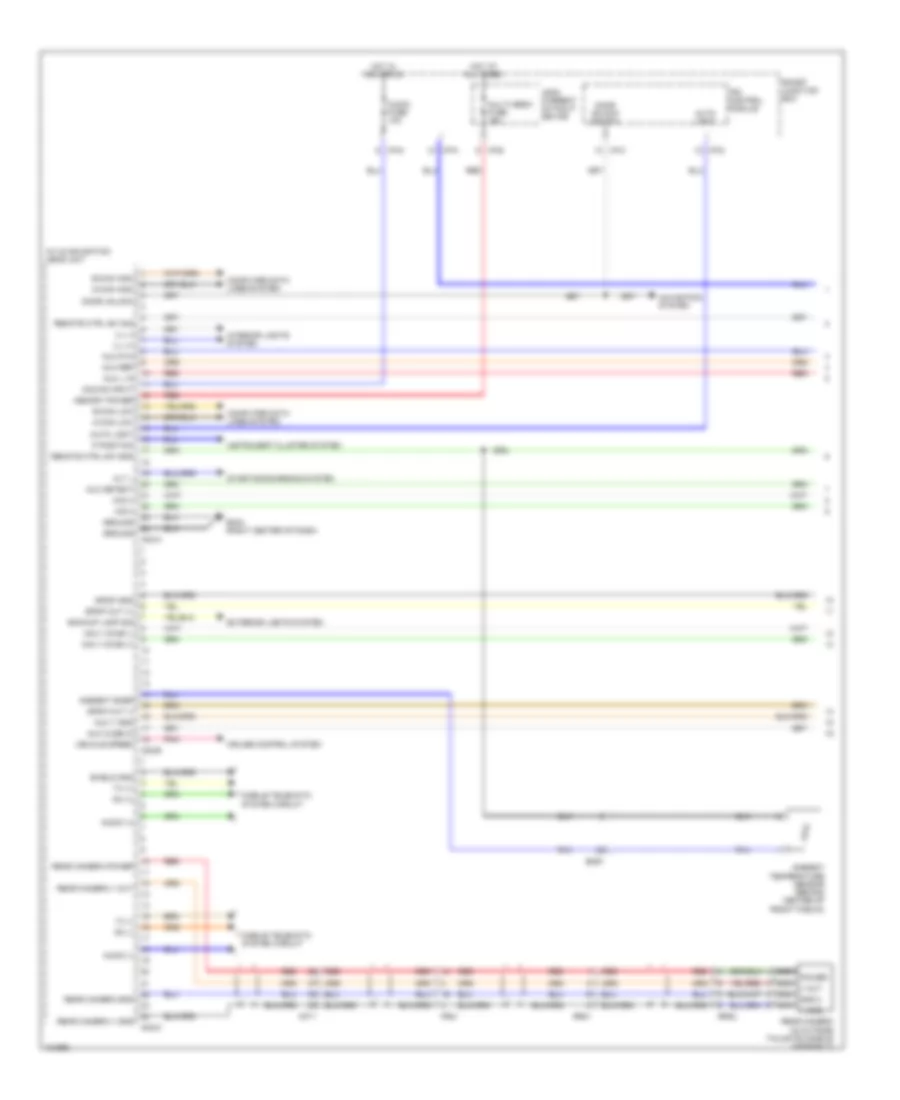
Navigation Wiring Diagram, with Amplifier (1 of 3) for Hyundai Veloster 2014
List of elements for Navigation Wiring Diagram, with Amplifier (1 of 3) for Hyundai Veloster 2014:
- A/v & navigation head unit
- Acc/on input
- Alt l
- Ambient snsr
- Ambient temperature sensor (behind center of front fascia)
- Audio (+)
- Audio (-)
- Audio fuse 10a
- Auto light
- Aux cusb in
- Aux detect
- Aux l in
- Aux r in
- Aux ref
- Aux v gnd
- B-can high
- B-can low
- Backup lamp sig
- Computer data lines system
- Cruise control system
- Door unlock
- Door unlock switch
- Em61
- Exterior lights system
- Fr21
- Gm04 (right center of dash)
- Ground
- Hot at all times
- Hot in acc or on
- I/p-c
- I/p-d
- I/p-e
- I/p-g
- I/p-k
- Ill (+)
- Ill (-)
- Instrument cluster system
- Interior lights system
- Ips control module
- Leak current autocut device
- M-can high
- M-can low
- M02-a
- M02-b
- M02-m
- Memory power
- Mf11
- Mic(+)
- Mic(-)
- Mobile telematic system circuit
- Multi media fuse 15a
- Navi voice (+)
- Navi voice (-)
- Navigation system
- Nca gnd 2
- Nca power
- Nca v gnd
- Nca v out
- P position
- Pnk
- Rear camera (in outside tailgate handle assembly)
- Rear camera gnd
- Rear camera power
- Rear camera v gnd
- Rear camera v out
- Red
- Remote ctrl sw gnd
- Remote ctrl sw sig
- Rr01
- Rr02
- Rx (+)
- Rx (-)
- Shield gnd
- Smart junction box
- Spdif gnd
- Spdif out (+)
- Spdif out (-)
- Starting/charging system
- Tx (+)
- Tx (-)
- Vehicle speed
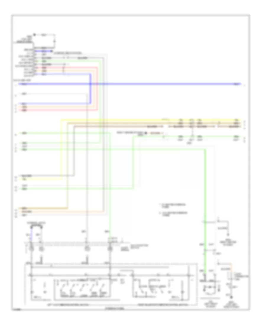
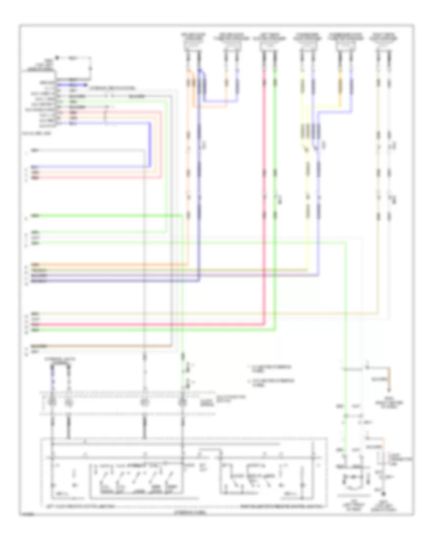
Navigation Wiring Diagram, with Amplifier (2 of 3) for Hyundai Veloster 2014
List of elements for Navigation Wiring Diagram, with Amplifier (2 of 3) for Hyundai Veloster 2014:
- (+)
- (-)
- (right center of dash) gm04
- 3ea ill
- 4ea ill
- Audio
- Audio (+)
- Audio (-)
- Aux & usb jack
- Aux detect
- Aux l in
- Aux r in
- Aux ref
- Aux shield gnd
- Aux v gnd
- Aux video in
- B/t
- B/t in
- Call
- Clock spring
- Down
- End of
- Gm01 (top left side of dash)
- Gm02 (top left side of dash)
- Gm04 (right center of dash)
- Ground
- Ill (+)
- Interior lights system
- Joint connector
- Left audio remote control switch
- M01-h
- M01-r
- Mf61
- Mic (+)
- Mic (-)
- Mic (left front of roof)
- Mode
- Mr11
- Multi-function switch
- Nca
- Out
- Red
- Seek
- Send
- Steering wheel
- Ura
- Voice
- Vol
- W/ heated steering wheel
- W/o heated steering
- Wheel
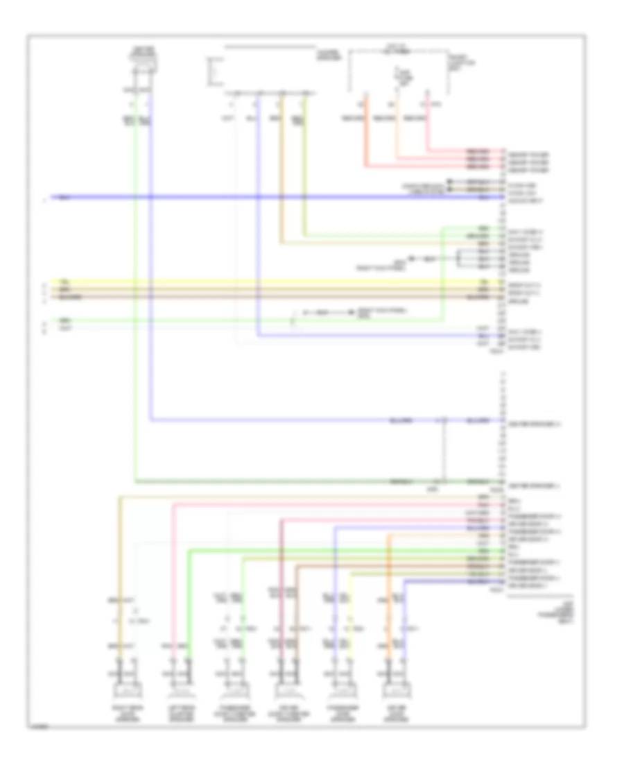
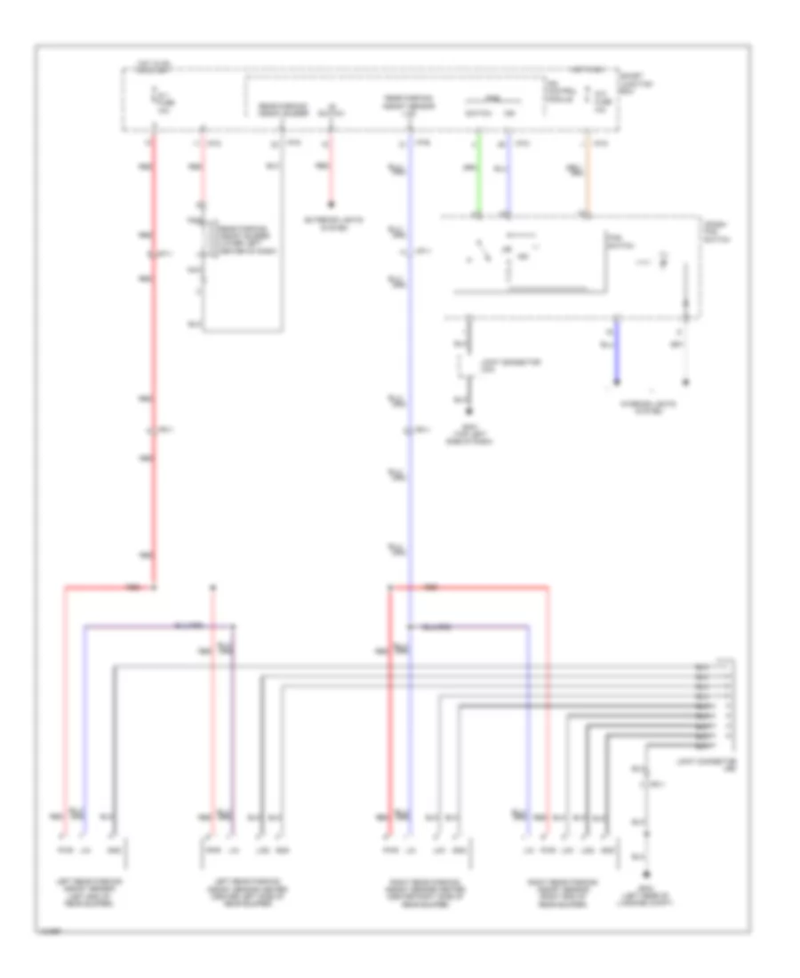
Navigation Wiring Diagram, with Amplifier (3 of 3) for Hyundai Veloster 2014
List of elements for Navigation Wiring Diagram, with Amplifier (3 of 3) for Hyundai Veloster 2014:
- (+)
- (-)
- (right kick panel) gf02
- Acc/on input
- Amp (under passenger's seat)
- Amp fuse 25a
- Center speaker
- Center speaker (+)
- Center speaker (-)
- Computer data
- Driver door (+)
- Driver door (-)
- Driver door speaker
- Driver door tweeter speaker
- F02-a
- F02-b
- F02-c
- Fd11
- Fd21
- Fd41
- Gf02 (right kick panel)
- Ground
- Hot at all times
- I/p-k
- Left rear quarter speaker
- Lines system
- M-can high
- M-can low
- Memory power
- Mf61
- Navi voice (+)
- Navi voice (-)
- Nca
- Passenger door (+)
- Passenger door (-)
- Passenger door speaker
- Passenger door tweeter speaker
- Pnk
- Right rear door speaker
- Rl(+)
- Rl(-)
- Rr(+)
- Rr(-)
- S/woof wl(+)
- S/woof wl(-)
- S/woof wr(+)
- S/woof wr(-)
- Smart junction box
- Spdif out (+)
- Spdif out (-)
- Woofer speaker
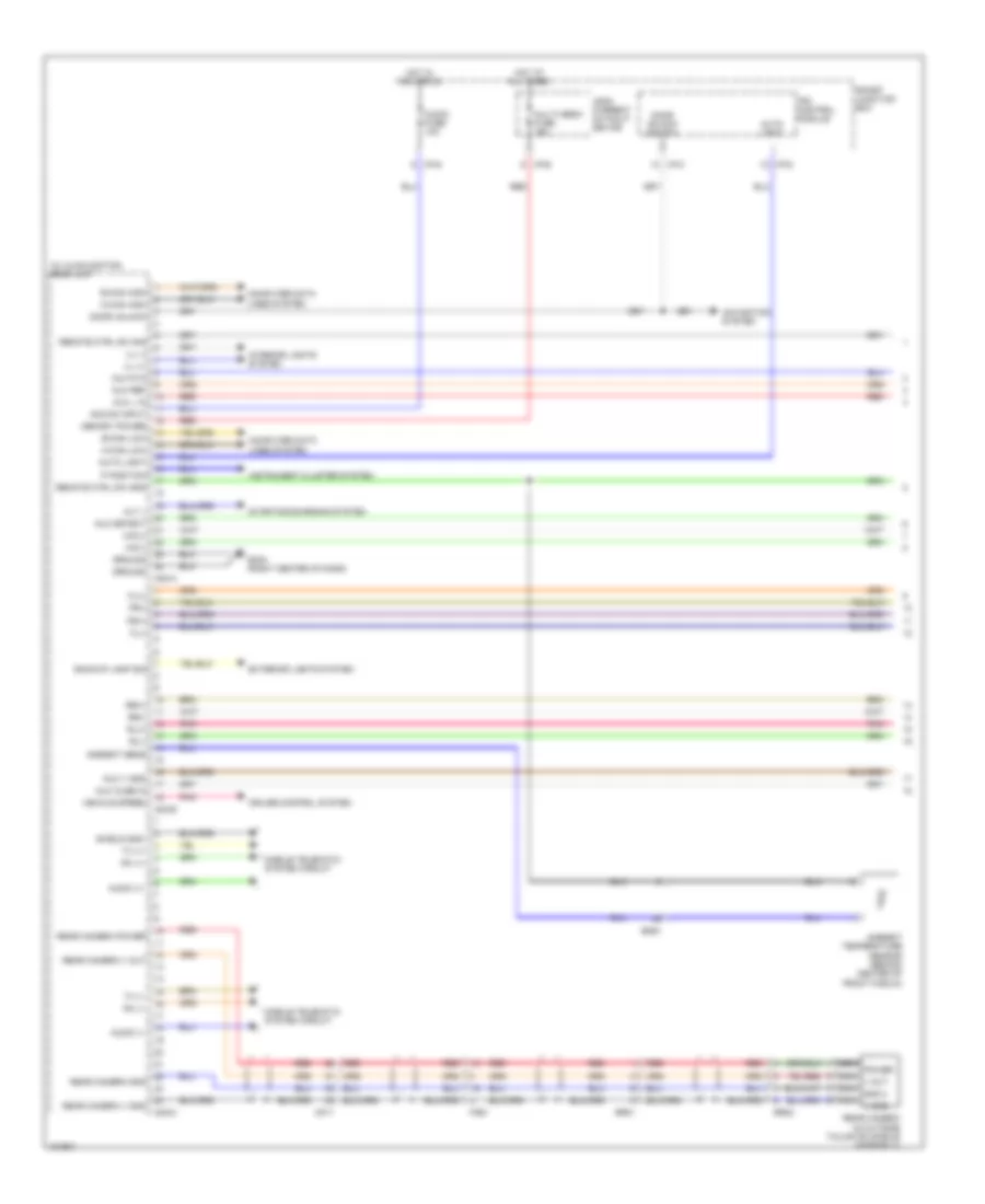
Navigation Wiring Diagram, without Amplifier (1 of 2) for Hyundai Veloster 2014
List of elements for Navigation Wiring Diagram, without Amplifier (1 of 2) for Hyundai Veloster 2014:
- A/v & navigation head unit
- Acc/on input
- Alt l
- Ambient sens
- Ambient temperature sensor (behind center of front fascia)
- Audio (+)
- Audio (-)
- Audio fuse 10a
- Auto light
- Aux cusb in
- Aux detect
- Aux l in
- Aux r in
- Aux ref
- Aux v gnd
- B-can high
- B-can low
- Backup lamp sig
- Computer data lines system
- Cruise control system
- Door unlock
- Door unlock switch
- Em61
- Exterior lights system
- Fl(+)
- Fl(-)
- Fr(+)
- Fr(-)
- Fr21
- Gm04 (right center of dash)
- Ground
- Hot at all times
- Hot in acc or on
- I/p-c
- I/p-d
- I/p-e
- I/p-g
- Ill (+)
- Ill (-)
- Instrument cluster system
- Interior lights system
- Ips control module
- Leak current autocut device
- M-can high
- M-can low
- M02-a
- M02-b
- M02-m
- Memory power
- Mf11
- Mic(+)
- Mic(-)
- Mobile telematic system circuit
- Multi media fuse 15a
- Navigation system
- Nca gnd 2
- Nca power
- Nca v gnd
- Nca v out
- P position
- Pnk
- Rear camera (in outside tailgate handle assembly)
- Rear camera gnd
- Rear camera power
- Rear camera v gnd
- Rear camera v out
- Red
- Remote ctrl sw gnd
- Remote ctrl sw sig
- Rl(+)
- Rl(-)
- Rr(+)
- Rr(-)
- Rr01
- Rr02
- Rx (+)
- Rx (-)
- Shield gnd
- Smart junction box
- Starting/charging system
- Tx (+)
- Tx (-)
- Vehicle speed
Navigation Wiring Diagram, without Amplifier (2 of 2) for Hyundai Veloster 2014
List of elements for Navigation Wiring Diagram, without Amplifier (2 of 2) for Hyundai Veloster 2014:
- (+)
- (-)
- 3ea ill
- 4ea ill
- Audio
- Audio (+)
- Audio (-)
- Aux & usb jack
- Aux detect
- Aux l in
- Aux r in
- Aux ref
- Aux shield gnd
- Aux v gnd
- Aux video in
- B/t
- B/t in
- Call
- Clock spring
- Down
- Driver door speaker
- Driver door tweeter speaker
- End of
- Fd11
- Fd21
- Fd41
- Gm01 (top left side of dash)
- Gm02 (top left side of dash)
- Gm04 (right center of dash)
- Ground
- Ill (+)
- Interior lights system
- Joint connector
- Left audio remote control switch
- Left rear quater speaker
- M01-h
- M01-r
- Mf11
- Mf61
- Mic (+)
- Mic (-)
- Mic (left front of roof)
- Mode
- Mr11
- Multi-function switch
- Nca
- Out
- Passenger door speaker
- Passenger door tweeter speaker
- Pnk
- Red
- Right rear door speaker
- Seek
- Send
- Steering wheel
- Ura
- Voice
- Vol
- W/ heated steering wheel
- W/o heated steering
- Wheel
Parking Assistant Wiring Diagram for Hyundai Veloster 2014
List of elements for Parking Assistant Wiring Diagram for Hyundai Veloster 2014:
- "r" switch
- (lin)
- 10a
- Crash pad switch
- Exterior lights system
- Fr11
- Gf03 (left rear of luggage compt)
- Gm01 (top left side of dash)
- Gnd
- Hot in on
- Hot in on or start
- I/p-b
- I/p-d
- I/p-g
- Ig 1 fuse 10a
- Ig 2 fuse
- Ill
- Ind
- Interior lights system
- Ips control module
- Joint connector uma
- Joint connector urc
- Left rear parking assist sensor (left end of rear bumper)
- Left rear parking assist sensor center (center left side of rear bumper)
- Lid1
- Lid2
- Lin
- Mf11
- Nca
- Pas
- Pas switch
- Pwr
- Rear parking assist buzzer
- Rear parking assist buzzer (lower left center of dash)
- Rear parking assist sensor
- Red
- Right rear parking assist sensor (right end of rear bumper)
- Right rear parking assist sensor center (center right side of rear bumper)
- Smart junction box
- Switch

 Čeština
 Dansk
Dansk Deutsch
 Ελληνικά
 English
 English
 Español
 Suomi
Suomi Français
 Français
 עברית
עברית Hrvatski
 Magyar
 日本語
日本語 한국어
한국어 Nederlands
 Polski
 Português
 Português
 Română
 Русский
 Slovenčina
 Slovenščina
 Svenska
 Türkçe
 中文 (中国)