POWER DISTRIBUTION
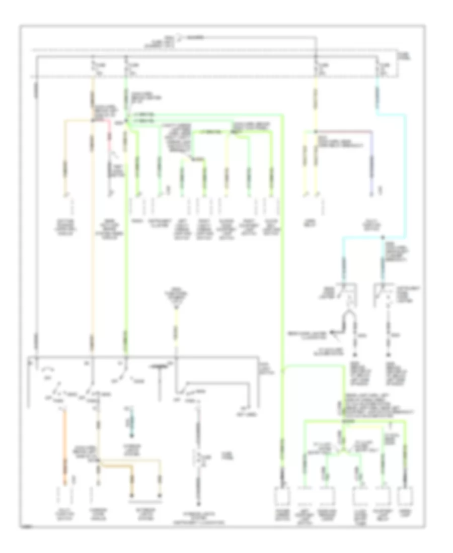
Power Distribution Wiring Diagram (1 of 3) for Ford Aerostar 1997
 https://portal-diagnostov.com/license.html
Automotive Electricians Portal FZCO
Automotive Electricians Portal FZCO
https://portal-diagnostov.com/license.html
https://portal-diagnostov.com/license.html
Automotive Electricians Portal FZCO
Automotive Electricians Portal FZCO
List of elements for Power Distribution Wiring Diagram (1 of 3) for Ford Aerostar 1997:
- (12 ga-
- (16 ga-
- (18 ga-
- (20 ga-
- (diagram 2 of 3)
- (eng cntrl sens harn, left rear of eng compt) s124
- (eng cntrl sensor harn, right front of eng compartment)
- (gen rectifier system harn, right front of eng compt)
- (main harn, behind center of i/p) s215
- (main harn, behind left kick panel)
- (main harn, behind left kick panel) s222
- (main harn, behind left side of i/p)
- (main harn, near data link connector breakout)
- (main harn, near inst cluster breakout) s272
- (main harn, near wiper control module breakout) s263
- (not used)
- (rabs) module breakout) s212
- (trailor lamp harn, near backup lamps relay breakout)
- 3.0l
- 4.0l
- A/c- heater control assembly
- Acc
- Air bag diagnostic monitor
- Auxiliary blower motor relay
- Backup lamps relay
- Battery
- Brake on/off (boo) switch
- C172
- C233
- C249
- C268
- Circuit breaker 14 20a
- Circuit breaker 2 6a
- Data link connector
- Digital trans- mission range (dtr) sensor
- Door lock/ unlock control relay
- Engine compartment relay box
- Fuel pump relay
- Fuse 10a
- Fuse 15a
- Fuse 20a
- Fuse link a
- Fuse link b
- Fuse link c
- Fuse link d
- Fuse link e
- Fuse link f
- Fuse link k
- Fuse panel
- Generator voltage regulator
- Ignition switch
- Illumi- nated entry timer
- In-line fuse 30a
- Instrument cluster
- Lock
- Master window/ door lock switch
- Multi- function switch
- Of i/p) s251
- Off
- Only
- Pcm inline fuse
- Pcm power relay
- Pnk
- Power door lock module
- Power- train control module (pcm)
- Radio
- Radio amplifier
- Rear anti- lock brake system (rabs) module
- Rear window defrost control
- Red
- Remote headphone module
- Right window/ door lock switch
- Run
- Running lamp relay
- S108
- S111 (engine control sensor harness, center of left fender)
- S133 (eng cntrl sensor harn, near starter relay breakout)
- S138 (eng cntrl sens harn, near starter relay breakout)
- S139
- S214 (main harn, behind left side of i/p)
- S221
- S269
- S280
- S410
- Sliding door ajar relay
- Speed control disable switch
- Speed control server/ amplifier assembly
- Sta
- Start
- Starter motor/ solenoid
- Starter relay
- To fuse panel
- To fuse panel (diagram 3 of 3)
- To fuse panel, and fuse link g, and instrument cluster (diagram 3 of 3)
- To main light switch (diagram 2 of 3)
- Wind- shield wiper motor
- Wiper control module
Power Distribution Wiring Diagram (2 of 3) for Ford Aerostar 1997
List of elements for Power Distribution Wiring Diagram (2 of 3) for Ford Aerostar 1997:
- (main harn, behind center of i/p)
- (main harn, behind left side of i/p) s216
- (main harn, behind left side of i/p) s219
- (main harn, behind right kick panel) s217
- (not used)
- (vanity mirror lamp feed harn, near right vanity mirror lamp and switch breakout)
- 22a
- C231
- C249
- Cargo lamp
- Courtesy lamp relay
- Daytime running lamps (drl) module
- Dimmer
- Dome
- Dome and reading lamps
- Exterior lights system
- From a fuse link a (diagram 1 of 3)
- From fuse panel (diagram 1 of 3)
- Fuse 15a
- Fuse 20a
- Fuse 30a
- Fuse 5a
- Fuse panel
- G206 (behind center of i/p, below left side of radio)
- Glove box lamp and switch
- Head
- Horn relay
- Ign
- Illumi- nated entry timer
- Instrument cluster
- Instrument panel cigar lighter
- Interior lights system
- Interior lights system (instrument illumination)
- Left courtesy lamp switch
- Left vanity mirror lamp and switch
- Main light switch
- Multi- function switch
- Nca
- Off
- Park
- Power mirror switch
- Radio
- Rear anti-lock brake system (rabs) module
- Rear cigar lighter
- Rear cigar lighter illumination
- Red
- Right courtesy lamp switch
- Right vanity mirror lamp and switch
- S202
- S218 (main harn, near horn relay breakout)
- S252
- S254
- S255 (main harn, near elect flasher breakout)
- S302
- S305
- Sliding door courtesy lamp switch
- Test conn- ector
- W/ auxiliary blower motor
- W/ dual rear door
- W/ illumi- nated entry only
- Warning chime module
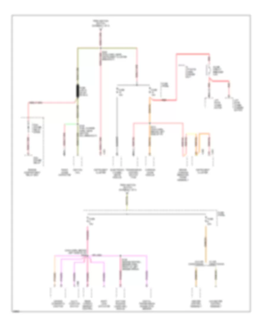
Power Distribution Wiring Diagram (3 of 3) for Ford Aerostar 1997
List of elements for Power Distribution Wiring Diagram (3 of 3) for Ford Aerostar 1997:
- (main harn, behind left side of i/p) s249
- A/c-heater control assembly
- Air bag diagnostic monitor
- Brake warning resistor/ diode assembly
- C250
- C251
- C268
- Daytime running lamps (drl) module
- Digital transmission range (dtr) sensor
- Electronic 4 wheel drive module
- Engine compartment relay box
- From ignition switch (diagram 1 of 3)
- Fuse 15a
- Fuse 30a
- Fuse panel
- Heater control assembly
- Ignition coil
- Inline circuit breaker 4.5a
- Instrument cluster
- Lift gate wiper motor
- Lift gate wiper/ washer switch
- Multi- function switch
- Nca
- Pcm power relay
- Pcm power relay diode
- Radio noise capacitor
- Rear window defrost control
- Red
- S109 (fuel charge harn, near ignition coil breakout)
- S136 (engine control sensor harn, front of left fender apron)
- S213 (main harn, behind left side of i/p)
- S220 (main harn, near instrument cluster breakout)
- Shift lock actuator
- Transmission control switch (tcs)
- W/ air conditioning
- W/ liftgate wiper/ washer only
- W/o air conditioning
- Warning chime module

 Čeština
 Dansk
Dansk Deutsch
 Ελληνικά
 English
 English
 Español
 Suomi
Suomi Français
 Français
 עברית
עברית Hrvatski
 Magyar
 日本語
日本語 한국어
한국어 Nederlands
 Polski
 Português
 Português
 Română
 Русский
 Slovenčina
 Slovenščina
 Svenska
 Türkçe
 中文 (中国)