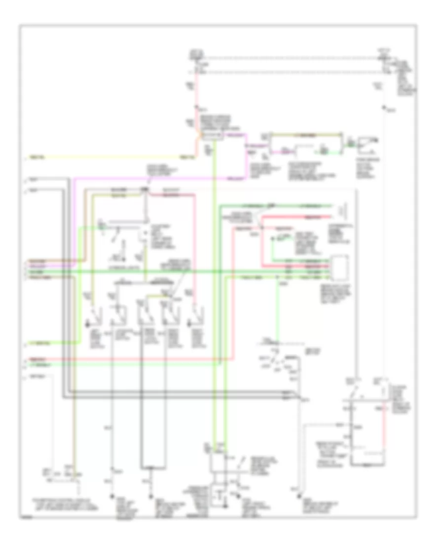
INSTRUMENT CLUSTER
Instrument Cluster Wiring Diagram (1 of 2) for Ford Aerostar 1997
 https://portal-diagnostov.com/license.html
Automotive Electricians Portal FZCO
Automotive Electricians Portal FZCO
https://portal-diagnostov.com/license.html
https://portal-diagnostov.com/license.html
Automotive Electricians Portal FZCO
Automotive Electricians Portal FZCO
List of elements for Instrument Cluster Wiring Diagram (1 of 2) for Ford Aerostar 1997:
- (behind center of i/p, below right side of radio)
- (main harn, below left side of i/p)
- (top left center of safety wall, near wiper motor)
- Above cowl panel)
- Acc
- Air bag diagnostic module (behind left side of i/p, near top of cowl panel)
- Air bag ind.
- Amp ind.
- Anti- slosh module
- Bat
- Brake ind.
- C249
- C250
- C251
- Column)
- Coolant temp. gauge
- Daytime running lamps module (front of left fender apron, forward of starter relay)
- Door ajar ind.
- Electronic 4 wheel drive ind.
- Electronic 4 wheel drive module (under right side of left front seat)
- Enable
- Enable psom programming connector (behind right cowl panel)
- Engine coolant temperature sender (3.0l-top center front of engine) (4.0l-top right front of engine)
- Engine oil pressure switch (3.0l-top of engine near valve cover) (4.0l-lower left front of engine, above engine oil pan)
- Fasten belts ind.
- Fuel gauge
- Fuel pump/fuel gauge sender (below rear of vehicle, top of fuel tank)
- Fuse 10a
- Fuse 15a
- Fuse 5a
- Fuse panel (behind left side side of i/p, left of steering
- G116
- G206
- Generator voltage regulator (top right front of engine)
- Gnd
- High beam ind.
- Hot at all times
- Hot in run
- Hot w/ lamp sw in park or head
- Ign
- Ign (run)
- Ignition switch
- Illumination lamps
- Instrument cluster
- Left turn ind.
- Lock
- Malfunction ind.
- Multi- function switch (top left side of steering column)
- Odometer select
- Off
- Ohms
- Oil press. gauge
- Programming
- Psom module
- Rear abs ind.
- Red/pnk
- Right turn ind.
- Run
- S201 (main harn, near speed control switch assembly)
- S209
- S211
- S220
- S254
- S275 (main harn, near breakout to cluster)
- S276
- S277
- Speed control amplifier (behind right side of i/p,
- Start
- Trip reset
- Volt- meter
- Vss input
- Vss output
- Vss return
- Warning chime module (behind left side of i/p, near top of cowl panel)
Instrument Cluster Wiring Diagram (2 of 2) for Ford Aerostar 1997
 https://portal-diagnostov.com/license.html
Automotive Electricians Portal FZCO
Automotive Electricians Portal FZCO
https://portal-diagnostov.com/license.html
https://portal-diagnostov.com/license.html
Automotive Electricians Portal FZCO
Automotive Electricians Portal FZCOList of elements for Instrument Cluster Wiring Diagram (2 of 2) for Ford Aerostar 1997:
- "b" pillar)
- (front of sliding door)
- (left rear corner of cargo area)
- (main harn, near breakout to cluster)
- (main harn, near breakout to ground g206)
- (rear harn, near breakout to license lmp)
- (rear of right
- (top left side of safety wall,
- Acc
- Brake fluid level switch (on brake master cylinder)
- Brake warning resistor/diode (taped to main harness, near g206)
- Button connectors
- Courtesy lamp relay
- Daytime running lamps module (front of left fender apron, forward of starter relay)
- Differential speed sensor (top of rear axle)
- Dss test connector (left rear of engine compt, on safety wall)
- Fuse
- Fuse 15a
- Fuse panel (behind left side of i/p, left of steering column)
- G100 (left front fender apron, left of battery)
- G206 (behind center of i/p, below left side of radio)
- G406 (top left side of rear door/ lift gate header)
- Gnd
- Hot in acc or run
- Hot in run or start
- Ignition switch
- Interior lights
- Left front door ajar switch
- Left of brake master cylinder)
- Liftgate ajar switch
- Lock
- Off
- Park brake
- Powertrain control module
- Pressure differential warning switch (below brake fluid reservoir)
- Rear anti-lock brake module (behind center of i/p, below ash tray)
- Rear door latch switch
- Red
- Red/pnk
- Right front door ajar switch
- Right rear door ajar switch
- Run
- S105
- S213
- S215
- S231
- S232
- S250
- S262
- S265
- S266
- S274
- S402
- S403
- S405
- Sliding door ajar relay (right of steering column)
- Start
- Switch (on park brake support)
- W/ drl
- W/ dual rear doors
- W/ liftgate
- W/o drl

 Čeština
 Dansk
Dansk Deutsch
 Ελληνικά
 English
 English
 Español
 Suomi
Suomi Français
 Français
 עברית
עברית Hrvatski
 Magyar
 Italiano
 日本語
日本語 Nederlands
 Polski
 Português
 Português
 Română
 Русский
 Slovenčina
 Slovenščina
 Svenska
 Türkçe
 中文 (中国)
