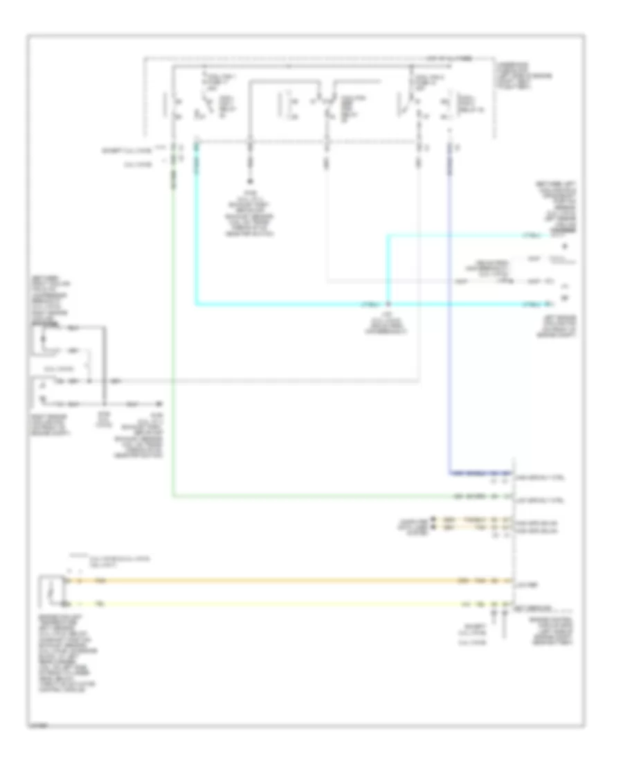
COOLING FAN
Cooling Fan Wiring Diagram, with Hybrid for Chevrolet Malibu LTZ 2008
 https://portal-diagnostov.com/license.html
Automotive Electricians Portal FZCO
Automotive Electricians Portal FZCO
https://portal-diagnostov.com/license.html
https://portal-diagnostov.com/license.html
Automotive Electricians Portal FZCO
Automotive Electricians Portal FZCO
List of elements for Cooling Fan Wiring Diagram, with Hybrid for Chevrolet Malibu LTZ 2008:
- (behind rear seat) generator battery vent fan
- (middle rear of engine) heater coolant pump
- (near windshield wiper fluid reservoir) g101
- (next to a/c compressor) starter generator control module (sgcm) coolant pump
- (right front of transmission, below sgcm) transmission pump
- (under right rear seat back) g301
- A trans pump driver error
- A12
- B pump control
- B10
- Bare
- Bas ign fuse 3 10a
- Bas pmps fuse 5 20a
- Battery positive vol
- C pump motor vol
- C12
- Computer data lines system
- Driver error
- Emission 2 fuse 5 10a
- Eng/tran cooling
- F trans pump low ref
- Fan control
- Fan tach feedback
- G trans pump high ref
- G107 (near sgcm cooling pump)
- Gen batt temp sens 1a control
- Gen batt temp sens 1b control
- Gen batt temp sens 2a control
- Gen batt temp sens 2b control
- Gen batt temp sens 3a control
- Gen batt temp sens 3b control
- Generator battery 1
- Generator battery 2
- Generator battery 3
- Generator battery assembly (behind rear seat, above spare tire)
- Generator battery disconnect control module
- Generator battery temperature sensor 1a
- Generator battery temperature sensor 1b
- Generator battery temperature sensor 2a
- Generator battery temperature sensor 2b
- Generator battery temperature sensor 3a
- Generator battery temperature sensor 3b
- Gnd
- Ground
- H trans pump sw control
- High speed gmlan serial data +
- High speed gmlan serial data -
- High vol
- Hot at all times
- Hot in run or start
- Ignition 1 vol
- Interlock loop sig
- Low ref
- Motor vol
- Nca
- Pnk
- Power
- Power distribution system
- Pump
- Pump control
- Pump driver (left front of engine, behind sgcm)
- Rear fuse block (in left side of luggage compt, behind left rear wheel well)
- Red
- Starter generator control module (sgcm) (in left front engine compt, behind headlamp assembly)
- Tan
- Trans pmp mtr relay
- Trans pump
- Trans pump mtr fuse 52 20a
- Trans pump rly coil control
- Underhood fuse block (on left side of engine compt)
- X2 interlock loop sig
Cooling Fan Wiring Diagram, without Hybrid for Chevrolet Malibu LTZ 2008
List of elements for Cooling Fan Wiring Diagram, without Hybrid for Chevrolet Malibu LTZ 2008:
- (2.4l (vin 5))
- (355 mm from main breakout) (2.4l (vin 5)) j153
- (between left cooling fan & crankshaft position sensor) (2.4l (vin 5)) left engine cooling fan diode
- (between right cooling fan & a/c compressor breakout) (2.4l (vin 5)) right engine cooling fan diode
- 2.4l (vin b)
- 2.4l (vin b) & 2.4l (vin 5) 3.6l (vin 7)
- 87a
- A11
- B10
- Computer data lines system
- Cool fan 1 fuse 17 30a
- Cool fan 2 fuse 18 30a
- Cool/ fan 1 relay
- Cool/ fan 2 relay 30
- Cool/fan ser/ par relay
- Ect sens sig
- Engine control module (ecm) (left side of engine compt, near battery)
- Engine coolant temperature (ect) sensor (2.4l (vin 5): below camshaft position exhaust sensor) (2.4l (vin b): on engine block, at left rear corner) (3.6l: on left side of front cylinder head, below throttle actuator control module)
- Except 2.4l (vin b)
- G106 (2.4l: at 4 exhaust port, above cmp exhaust sensor) (3.6l: on trans- mission stud, near pnp switch)
- High spd gmlan
- High spd rly ctrl
- Hot at all times
- J151 (2.4l (vin 5)) (305 mm from main breakout)
- Left engine cooling fan (on front of engine compt)
- Low ref
- Low spd rly ctrl
- Right engine cooling fan (on front of engine compt)
- S152 (2.4l (vin 5))
- Tan
- Underhood fuse block (left side of engine compt, next to battery)

 Čeština
 Dansk
Dansk Deutsch
 Ελληνικά
 English
 English
 Español
 Suomi
Suomi Français
 Français
 עברית
עברית Hrvatski
 Magyar
 Italiano
 日本語
日本語 한국어
한국어 Nederlands
 Português
 Português
 Română
 Русский
 Slovenčina
 Slovenščina
 Svenska
 Türkçe
 中文 (中国)