ANTI-LOCK BRAKES
Anti-lock Brakes Wiring Diagram (1 of 2) for Hummer H3 2006

List of elements for Anti-lock Brakes Wiring Diagram (1 of 2) for Hummer H3 2006:
- (below driver seat) (w/o active brakes) longitudinal accelerometer sensor
- (on left inner front wheel well) g105
- 5v ref
- Abs/vses fuse 29 10a
- Abs/vses1 -sol -mtr fuse 67 40a
- Abs/vses2 -mtr -sol fuse 64 30a
- Batt +
- Bkup volt
- Brake fluid level switch (on left side of brake fluid reservoir)
- Brk fld sig
- Can h
- Can l
- Dlvrd torq sig
- Early prod late prod
- Electronic brake control module (ebcm) (left of master cylinder)
- Exterior lights system
- G105 (on left inner front wheel well)
- Grd
- Hot at all times
- Hot run/crnk relay energized
- Ign 1 volt
- Ign 3 volt
- Las sig
- Left front wheel speed sensor (on left front wheel hub)
- Left rear wheel speed sensor (on left side of rear axle)
- Lf spd low ref
- Lf spd sig
- Low ref
- Lr spd low ref
- Lr spd sig
- Pnk
- Red
- Req torq sig
- Rf spd low ref
- Rf spd sig
- Right front wheel speed sensor (on right front wheel hub)
- Right rear wheel speed sensor (on right side or rear axle)
- Rr spd low ref
- Rr spd sig
- S110
- S215 (in body harness)
- Serial class 2
- Steering pos sig
- Steering sig a
- Steering sig b
- Stop fuse 1 20a
- Stop lamp switch (above brake pedal assembly)
- Stop lp volt
- Tan
- Underhood fuse block (above left front wheel well)
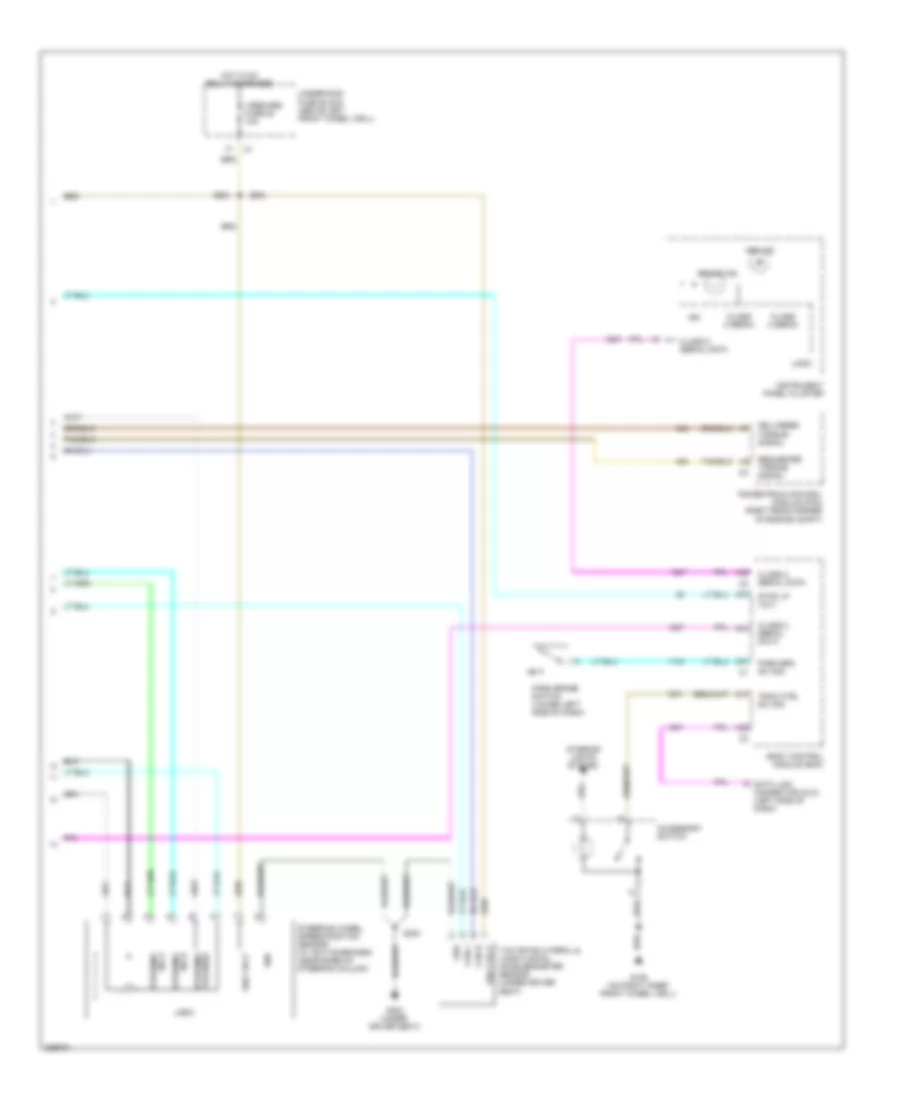
Anti-lock Brakes Wiring Diagram (2 of 2) for Hummer H3 2006
List of elements for Anti-lock Brakes Wiring Diagram (2 of 2) for Hummer H3 2006:
- A17
- A31
- A37
- A38
- A39
- A41
- Abs ind
- Accessory switch
- Body control module (bcm)
- Brake ind
- Can h
- Can l
- Class 2 (ebcm)
- Class 2 serial data
- Data link connector (dlc) (left side of dash)
- Delivered torque signal
- G106 (on right inner front wheel well)
- G300 (under driver seat)
- Grd
- Hot hvac relay energized
- Ign
- Ign 3 volt
- Instrument panel cluster
- Interior lights system
- Logic
- Park brake switch (lower left side of dash)
- Park brk sw sig
- Powertrain control module (pcm) (right rear corner of engine compt)
- Requested torque signal
- S300
- Steering pulsesig
- Steering sig a
- Steering sig b
- Steering wheel speed/position sensor (w/ active brakes) (near base of steering column)
- Stop lp volt
- Trac ctrl sw sig
- Underhood fuse block (above left front wheel well)
- Vses/abs fuse 52 10a
- Yaw rate/lateral & longitudinal accelerometer sensor (under driver seat)