ENGINE PERFORMANCE
3.5L VIN 6
3.5L VIN 6, Engine Performance Wiring Diagram (1 of 5) for Hummer H3 2006

List of elements for 3.5L VIN 6, Engine Performance Wiring Diagram (1 of 5) for Hummer H3 2006:
- (behind glove box) transfer case shift control module
- (chassis harness, approx 22.5 cm (8.9 in) from fuel pump & sender assembly conn)
- (in body harn, approx 14 cm (5.5 in) to right of stop lamp switch breakout in main harn)
- 4wd lo sw
- A/c comp rly
- A/c press
- A/c refrigerant pressure sensor (on high pressure hose connection to compressor)
- Accelerator pedal position (app) sensor (on accelerator pedal bracket)
- Accy voltage
- Air conditioning system
- App 1 +5v ref
- App 1 low ref
- App 2 +5v ref
- App 2 low ref
- App sens 1
- App sens 2
- Arp +5v ref
- Arp low ref
- Battery b+
- Class 2 data
- Clstr fuse 19 10a
- Cnstr vent fuse 31 10a
- Computer data lines system
- Cpp sw sig
- Cruise control system
- Cruise ctrls
- Diag enable
- Evap vent sol
- Evaporative emission (evap) canister vent solenoid (above spare tire)
- Exterior lights system
- Ftp +5v ref
- Fuel lvl sens
- Fuel pump rly
- Fuel tank press
- Fuel tank pressure (ftp) sensor (top of fuel pump & sender assembly)
- Hot at all times
- Hot in run & start
- Ignition 1
- Instrument panel cluster
- Low ref
- Malfunction indicator lamp (mil)
- Mil ctrl
- Pcm 1 fuse 21 10a
- Pcm b fuse 30 10a
- Pnk
- Pnp/clutch sig
- Powertrain control module (pcm) (left front side of engine compt)
- S215
- S359
- Starter rly
- Starting/ charging system
- Stop fuse 54 15a
- Stop lamp
- Stop lamp switch (above brake pedal assembly)
- Tan
- Tcc brk sw
- Underhood fuse block (above left front wheel well)
3.5L VIN 6, Engine Performance Wiring Diagram (2 of 5) for Hummer H3 2006
List of elements for 3.5L VIN 6, Engine Performance Wiring Diagram (2 of 5) for Hummer H3 2006:
- (on left inner front wheel well, behind battery)
- Acc
- Accy input
- Accy output
- Body control module (bcm) (behind right front kick panel)
- Electronic brake control module (ebcm) (left of master cylinder) c2
- Etc fuse 46 15a
- Fuel pmp fuse 3 15a
- Fuel pump & sender assembly (top of fuel tank)
- Fuel pump relay
- G105
- G420 (mounted to left side of rear crossmember)
- Heated oxygen sensor (ho2s) 1 (on exhaust manifold, on right side of engine)
- Heated oxygen sensor (ho2s) 2 (in exhaust pipe, adjacent to transmission)
- Hot at all times
- Ignition switch
- Lock
- Nca
- O2 snsr fuse 47 10a
- Off
- Pnk
- Pwr/ trn relay
- Run
- Start
- Underhood fuse block (above left front wheel well)
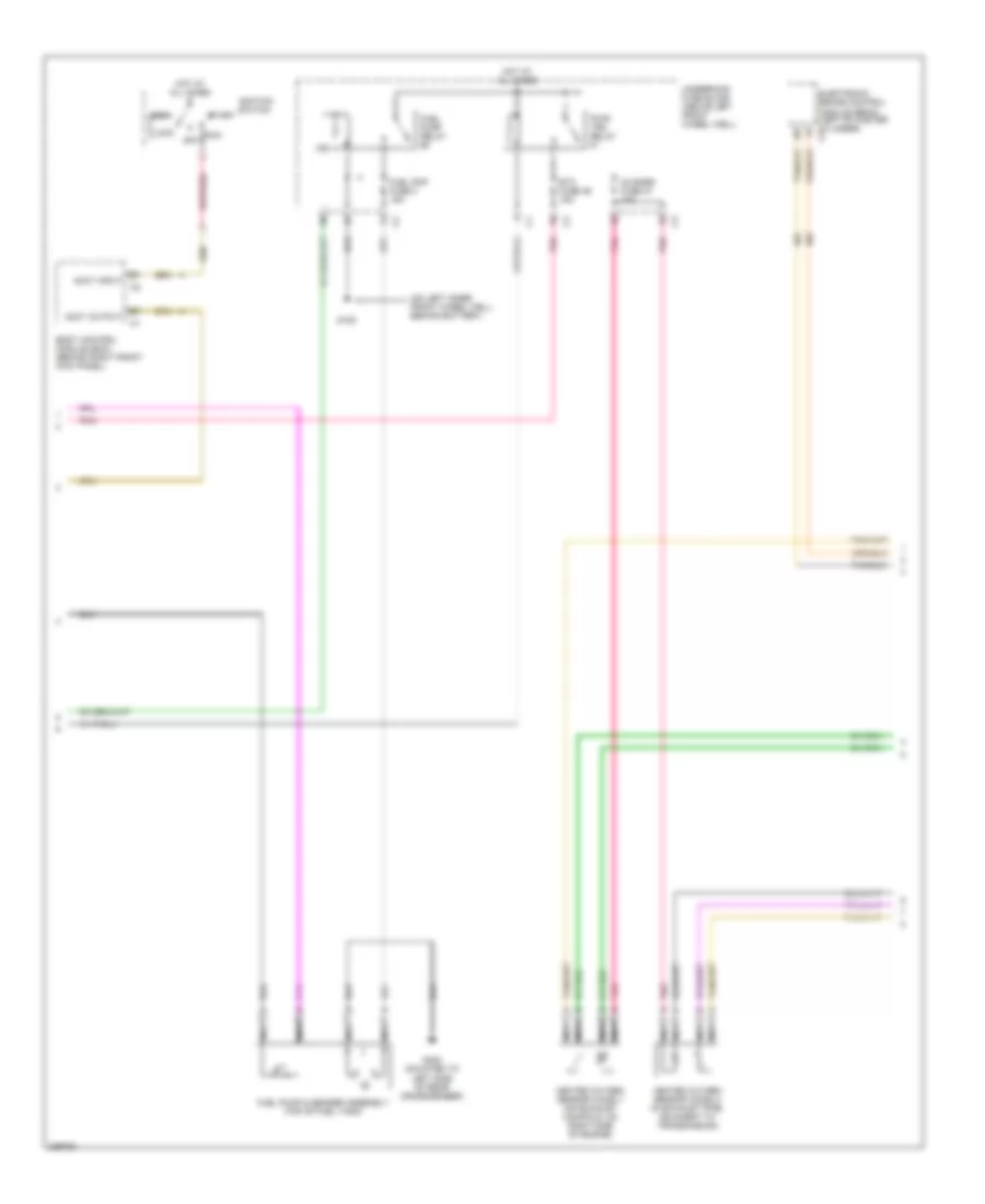
3.5L VIN 6, Engine Performance Wiring Diagram (3 of 5) for Hummer H3 2006
List of elements for 3.5L VIN 6, Engine Performance Wiring Diagram (3 of 5) for Hummer H3 2006:
- 1-2 sol
- 2-3 sol
- 3-2 sol
- A/t fluid pressure manual valve position switch
- Automatic transaxle
- Del torque
- Engine oil pressure (eop) switch (above oil filter)
- Evap purge
- Fluid temp sensor
- Ho2s 2 hi
- Ho2s 2 htr
- Ho2s 2 low
- Low oil sw
- Low ref
- Oil press
- Park/neutral position (pnp) switch (left side of automatic transmission)
- Pc sol
- Pnk
- Powertrain control module (pcm) (left front side of engine compt)
- Pressure control solenoid
- Red
- Req torque
- Rev
- S133
- Tan
- Tcc pwm sol
- Tcc sol
- Tfp sw a
- Tfp sw b
- Tfp sw c
- Tft sens
- Tr sw a
- Tr sw b
- Tr sw c
- Tr sw p
- Vehicle speed sensor (vss) (left rear of transfer case)
- Vss sig hi
- Vss sig low
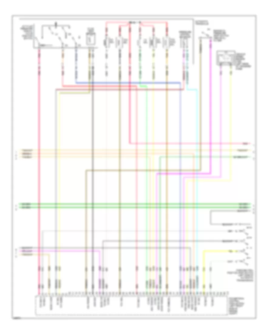
3.5L VIN 6, Engine Performance Wiring Diagram (4 of 5) for Hummer H3 2006
List of elements for 3.5L VIN 6, Engine Performance Wiring Diagram (4 of 5) for Hummer H3 2006:
- (above left front wheel well) underhood fuse block
- Control
- Eng cntrl sys fuse 22 15a
- Evaporative emission (evap) canister purge solenoid (below intake, in back of alternator)
- G102 (lower left side of engine, rearward of g103)
- G103 (lower left side of engine, forward of g102)
- Ground
- Hot in run & start
- Iat
- Ign fuse 33 15a
- Ignition
- Ignition coils (in center front of cam cover)
- Inj fuse 23 15a
- Intake air temperature (iat)/ mass air flow (maf) sensor (between air cleaner and throttle body)
- Maf
- Nca
- Plug
- Pnk
- Spark plug
- Tan
- Trans fuse 34 10a
- Underhood fuse block (above left front wheel well)
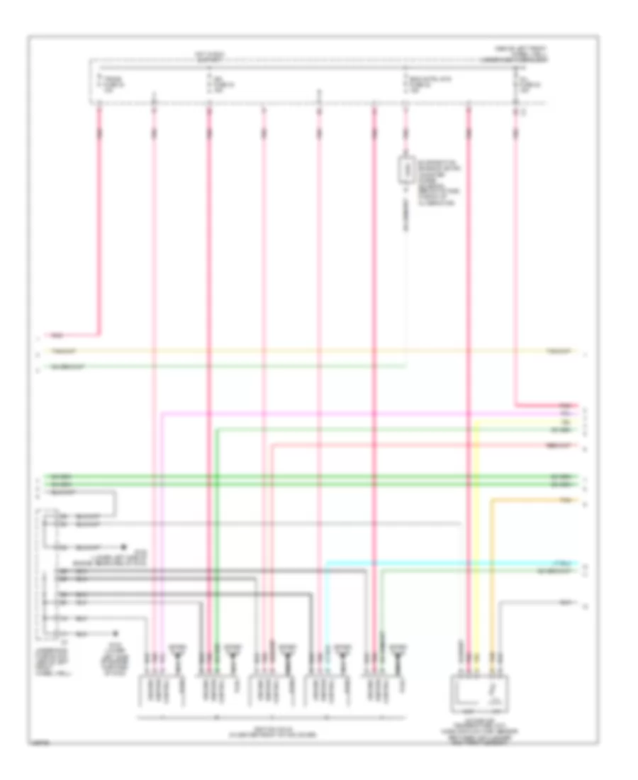
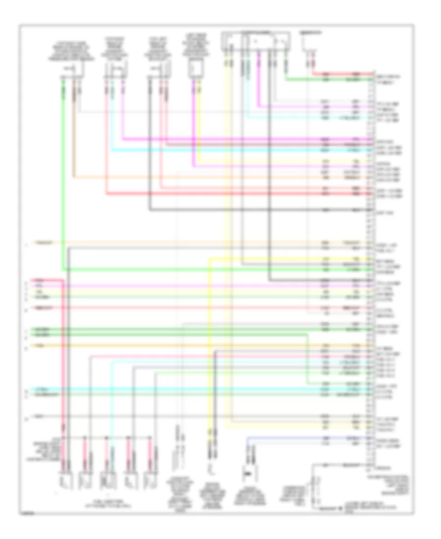
3.5L VIN 6, Engine Performance Wiring Diagram (5 of 5) for Hummer H3 2006
List of elements for 3.5L VIN 6, Engine Performance Wiring Diagram (5 of 5) for Hummer H3 2006:
- (left rear of engine block, below starter) crankshaft position (ckp) sensor
- (lower left side of engine, rearward of g103) g102
- (top left front of engine) camshaft position (cmp) (exhaust)
- (top right front of engine) camshaft position (cmp) (intake)
- (top right side rear of engine, on intake manifold) manifold absolute pressure (map) sensor
- Camshaft position (cmp) actuator solenoid bank 1 exhaust (right front of cylinder head)
- Ckp low ref
- Ckp sig
- Cmp 1 sig
- Cmp 2 sig
- Cmp1 +12v ref
- Cmp1 low ref
- Cmp2 +12v ref
- Cmp2 low ref
- Cpa +5v ref
- Cpa low ref
- Ect low ref
- Ect sens
- Engine coolant temperature (ect) sensor (top rear center of engine)
- Fuel inj 1
- Fuel inj 2
- Fuel inj 3
- Fuel inj 4
- Fuel inj 5
- Fuel injectors (attached to fuel rail)
- Gen field
- Gen turn-on
- Generator
- Ground
- Ho2s 1 high
- Ho2s 1 htr
- Ho2s 1 low
- Iat low ref
- Iat sens
- Ic 1 ctrl
- Ic 2 ctrl
- Ic 3 ctrl
- Ic 4 ctrl
- Ic 5 ctrl
- Knock sens
- Knock sensor (ks) (below intake manifold, near front of engine)
- Ks 1 low ref
- Maf sens
- Map +5v ref
- Map low ref
- Map sens
- Nca
- Pnk
- Pnk a
- Powertrain control module (pcm) (left front side of engine compt)
- Red
- S103 (engine compt harn, near grille lamps relay, by master cylinder)
- Tac mtr 1
- Tac mtr 2
- Tan
- Throttle body
- Tp 1 +5v ref
- Tp 1 low ref
- Tp 2 +5v ref
- Tp 2 low ref
- Tp sens 1
- Tp sens 2
- Underhood fuse block (above left front wheel well)