CRUISE CONTROL
Cruise Control Wiring Diagram for Hummer H3 2006
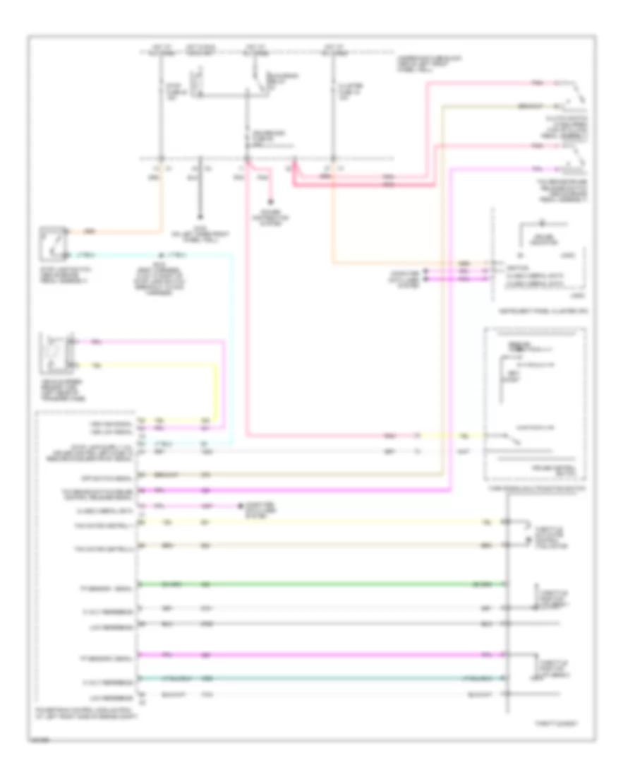
List of elements for Cruise Control Wiring Diagram for Hummer H3 2006:
- 5 volt reference
- Class 2 serial data
- Cluster fuse 19 10a
- Clutch switch (if equipped) (top of clutch pedal assembly)
- Coast
- Computer data lines system
- Cpp switch signal
- Cruise control switch
- Cruise indicator
- Cruise/misc fuse 35 10a
- G105 (on left inner front wheel well)
- Hot at all times
- Hot in run or start
- Ignition
- Instrument panel cluster (ipc)
- Logic
- Low reference
- Pnk
- Power distribution system
- Powertrain control module (pcm) (at left front side of engine compt)
- Resume/ accel
- Run/crank relay
- S215 (body harness, 14 cm to right of stop lamp switch breakout in main harness)
- Set/
- Stop fuse 54 15a
- Stop lamp switch (above brake pedal assembly)
- Tac motor control-1
- Tac motor control-2
- Tcc brake switch/cruise control release signal
- Tcc brake/cruise release switch (above brake pedal assembly)
- Throttle actuator control (tac) motor
- Throttle body
- Throttle position (tp) sens 1
- Throttle position (tp) sens 2
- Tp sensor 1 signal
- Tp sensor 2 signal
- Turn signal/multifunction switch
- Underhood fuse block (above left front wheel well)
- Vehicle speed sensor (vss) (left rear of transfer case)
- Vss high signal
- Vss low signal
 English